Foot roll support frame with multi-section short-side foot rolls

A segmented, support frame technology, applied in the field of support frames, can solve the problems of not being able to improve the inhibition of foot rolls, achieve the effects of improving production safety and avoiding steel leakage accidents

Active Publication Date: 2013-01-02
BAOSHAN IRON & STEEL CO LTD
View PDF3 Cites 2 Cited by
  • Summary
  • Abstract
  • Description
  • Claims
  • Application Information

AI Technical Summary

Problems solved by technology

Both domestic patents CN2206686 and CN201201042 realize the optimization of the side support of the slab by directly changing the shape of the foot roll surface, but they cannot get rid of the fundamental problem that the foot roll surface is "too narrow" to cause the over angle; at the same time, foreign patents GB2326364, JP2003048046 and JP2003164950 all have small changes in the current foot roll form, such as changing the straight roll surface to an arc-shaped convex roll surface, or processing a stepped convex roll surface. These roll surface forms are not Can not improve the inhibition effect of the foot roller on the "super angle" of the edge

Method used


Image

  • Foot roll support frame with multi-section short-side foot rolls
  • Foot roll support frame with multi-section short-side foot rolls
  • Foot roll support frame with multi-section short-side foot rolls

Examples


Embodiment Construction

[0027] Below, according to Figure 4 ~ Figure 8 The specific structure and beneficial effect of the foot roller supporting frame (hereinafter referred to as "foot roller supporting frame") with multiple segmented short side foot rollers of the present invention will be described.

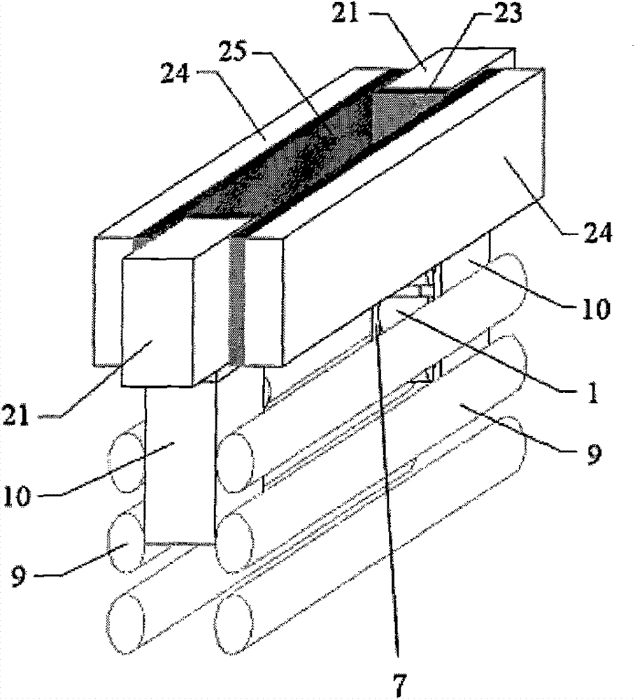
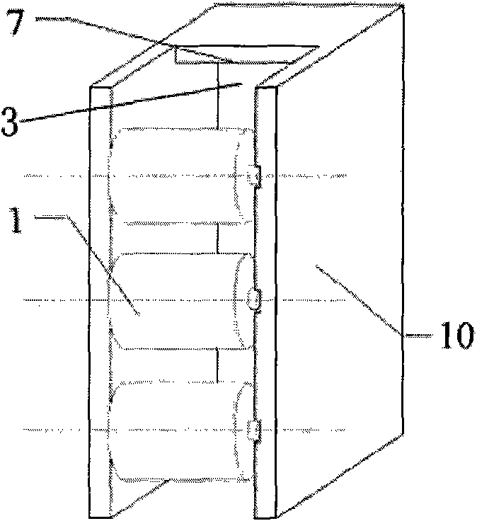
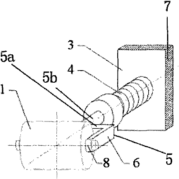
[0028] Figure 4 It is a partially cutaway perspective view showing the front end side of the right frame side wall 10b of the foot roller support frame of the present invention. Such as Figure 4As shown, the foot roller support frame 7 of the present invention is composed of a left frame side wall 10a, a right frame side wall 10b and a bracket side wall 11 integrated with the rear end sides of these left and right frame side walls. More than three (at least three, shown as three) foot roller assemblies g are arranged in sequence from top to bottom on the wall surface 3, and each foot roller assembly g includes: short-side foot roller 1; foot roller support part 5, which The arm is supported by ...


PUM


Abstract

The invention discloses a foot roll support frame with multi-section short-side foot rolls. The inner wall surface (3) of a bracket side wall (11) is provided with more than three foot roll components (g) in sequence from up to down; each foot roll component comprises a short side foot roll (1), a foot roll bracket part (5) and a buffer spring (4); the foot roll bracket part (5) consists of two oppositely parallel root roll support arms (6), a cross frame (5a) and a strut (5b); one end of the buffer spring is fixed on the inner wall surface; the other end of the buffer spring is connected with the strut; the strut deviates from the center of the cross frame and is formed on one end of the cross frame; the short side foot roll comprises a short foot roll (1a), a medium foot roll (1b) and along foot roll (1c) which are respectively connected into a whole body by two shaft necks; the shaft necks are respectively, rotatably and freely arranged on the other ends of the two foot roll support arms, and are mounted as follows: the shaft necks in each pair of foot roll components are staggered with the shaft necks of the neighboring foot roll component. The foot roll support frame with the multi-section short-side foot rolls can inhibit the exceeding corners at the side surface of a casting blank shell, improve the angle quality of the casting blank, avoid bleed-out accident, and improve the production safety.

Description

technical field [0001] The invention relates to a support frame, in particular to a foot roller with multiple segmented short-side foot rollers used by the main equipment of a continuous casting machine, which uses foot rollers to continuously support the soft casting slab pulled out from the bottom of the short-side copper plate of the crystallizer Roll support frame. Background technique [0002] Hydraulic slab continuous casting mold (slab continuous casting machine) such as figure 1 As shown, a kind of foot roll supporting frame 7 is used, and a plurality of short side foot rolls 1 (also called short side foot rolls of continuous casting machine) are supported on the rear side inner wall 3 of its frame side wall 10, for continuously supporting just The thin slab shell (primary solidification slab shell) casting slab separated from the copper plate of the mold has a very harsh working environment, because the surface temperature of the slab shell is extremely high, basic...

Claims


Application Information

Patent Timeline
Patent Type & Authority Patents(China)
IPC IPC(8): B22D11/06
Inventor 段明南杨建华冯长宝
Owner BAOSHAN IRON & STEEL CO LTD
Why Eureka
Try Eureka