
Automatic tube feeding device for hose assembly machine

An assembly machine, automatic feeding technology, applied in the direction of metal processing, metal processing equipment, manufacturing tools, etc., can solve the problems of easy work injury and failure, affecting production efficiency, etc., to improve assembly quality, improve production efficiency, clamping position precise effect

Active Publication Date: 2011-08-17
浙江本发科技有限公司
View PDF4 Cites 13 Cited by
  • Summary
  • Abstract
  • Description
  • Claims
  • Application Information

AI Technical Summary

Problems solved by technology

It takes only 4 seconds to complete the complete assembly of the ferrule, nut and core on the assembly machine, but the time to place and take out the braided hose is much longer, and it is also required to strictly align and clamp the hose when placing The position, eyesight and spirit need to be highly concentrated, which not only affects the production efficiency, but also firmly binds the operator to the machine table, and cannot leave every second. Repeating this tedious and monotonous action of putting and taking tubes, a little If you are not careful, it is easy to cause work-related injuries and malfunctions

Method used


Image

  • Automatic tube feeding device for hose assembly machine
  • Automatic tube feeding device for hose assembly machine
  • Automatic tube feeding device for hose assembly machine

Examples


Embodiment Construction

[0028] Further elaborate the present invention below in conjunction with embodiment and accompanying drawing:

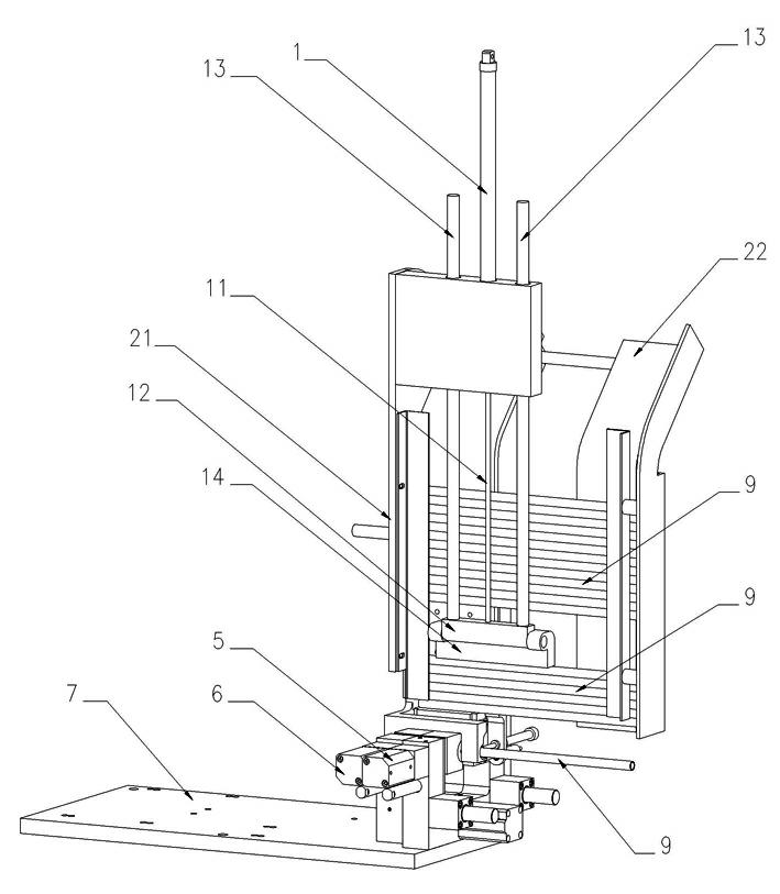
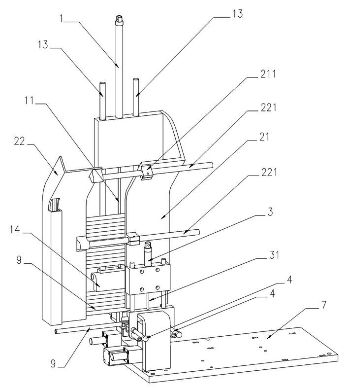
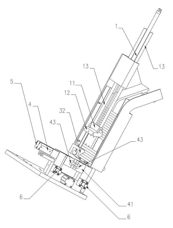
[0029] Such as Figure 1 to Figure 5 The working process of the automatic tube feeding device of the hose assembly machine shown is as follows: the operator arranges the fixed-length hose 9 on the fixed backing 21 of the hose arrangement frame 2, and arranges the ferrules on the ferrule chute Inside, set the nut and core together and arrange them on the vertical nut core slideway; select the process parameters on the microcomputer touch screen according to the model specification of the hose, and then start the machine.

[0030] The push rod of the push tube cylinder 1 stretches out, and the push tube seat 11 fixed on the front end of the push rod drives the pin-connected push tube rack 12 to push down the entire row of hoses 9 arranged on the fixed backing 21 with a constant air pressure. , so that the lowermost hose is accurately positioned on the pipe-taking posi...


PUM


Abstract

The invention discloses an automatic tube feeding device for a hose assembly machine. The automatic tube feeding device comprises a tube pushing cylinder, a hose array rack, a tube pushing rack, a mechanical finger, a mechanical hand rack, a manipulator opening and closing cylinder, a manipulator lifting cylinder, a tube clamping cylinder, a tube clamping fixing die and a tube clamping moving die; the tube pushing rack fixed on a mandrel of the tube pushing cylinder pushes the arrayed hoses downwards to the bottom; and the mechanical finger and the mechanical hand rack continuously clamp the bottommost hose, push the bottommost hose forwards, and descend simultaneously after leaving the tube picking position to delivery the hose to an assembly position. A micro computer instructs a tube clamping moving seat and a tube reducing moving die to fold transversely towards a tube clamping fixing seat and a tube reducing fixing die, the mechanical finger draws back, the two dies hold the hose simultaneously, and the tube clamping seat clamps the hose firmly, and loosens the hose to be reset until the next assembly procedure is completed. When the manipulator picks up all the hoses on the hose array rack, the tube pushing cylinder lifts the tube pushing seat, slides the tube pushing seat through the whole row of hoses, and drags the tube pushing seat to a gap at the upper end; and the tube pushing rack resets, and pushes the hose downwards while jacking the hose.

Description

technical field [0001] The invention relates to a hose processing machine, in particular to an automatic pipe feeding device for a hose assembly machine. Background technique [0002] At present, in the production of the hose industry, the assembly method of the hose is mostly based on manual operation. The work content is to fix the three parts of the ferrule, core and nut at each top of the hose, and require the nut to be able to rotate. But cannot move. [0003] During the above-mentioned operation process, since the braid of the hose braid elastically disperses at the incision site, it is very sharp, and workers are often stabbed by metal wires and bloody when assembling the collar, and have to replace them. If you want to wear stab-resistant gloves to work, the product quality cannot be guaranteed due to clumsy movements and low efficiency, and the production cost remains high. The patent application No. 201010500310.1 discloses "A Semi-automatic Assembly Machine for ...

Claims


Application Information

Patent Timeline
IPC IPC(8): B23P19/04
Inventor 梁贤军万春明薛林晓
Owner 浙江本发科技有限公司
Learn More