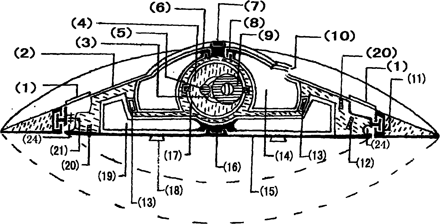
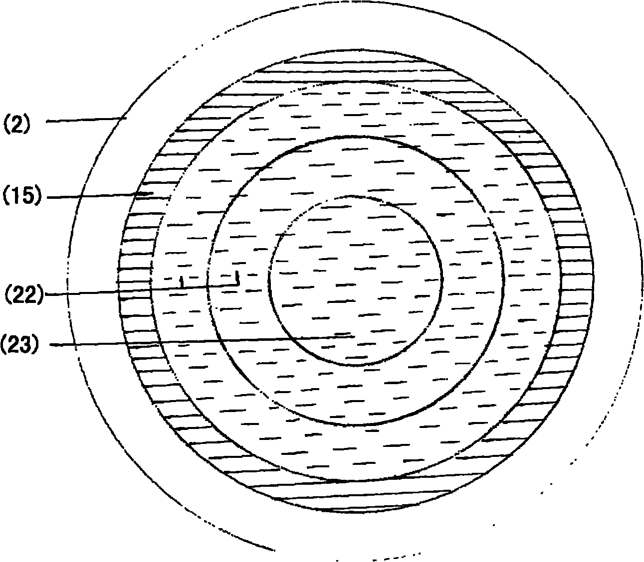
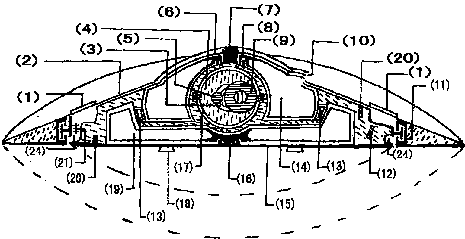
(2) Power system: It is mainly composed of magnetic levitation wheel ring, central axis of flying saucer, transfer cabin, flying saucer cockpit, transparent vacuum cover, air compressor, universal force applicator and other components. Magnetic levitation, electric motor and other technologies are used to make the flying saucer The special outer cover and the flying saucer cockpit rotate rapidly around the central axis of the flying saucer, but one of the rotating directions is clockwise and the other two are counterclockwise, which can automatically offset the reaction torque generated when each other rotates, so that the central axis automatically Keeping it in a non-rotating state, one of the rotor motors is connected to the central axis of the flying saucer and the special cover on the flying saucer (1. It has a protective function. 2. It can efficiently convert visible light and invisible infrared rays of light energy into electrical energy. 3. It can be transmitted through Through the glass of the flying saucer cockpit, the transparent vacuum cover and the special outer cover to clearly see the situation of part of the space outside the flying saucer) together, it can drive the special outer covering of the flying saucer to rotate, and the other rotor motor is assembled with one of the flying saucer cockpit and the central axis of the flying saucer Together, they can drive the lower UFO cockpit to rotate, while the outer rotor motor is assembled with another UFO cockpit and the central axis of the UFO, which can control the rotation of the UFO cockpit above. By means of communication, when the UFO cockpit rotates, part of the gravity will be divided into centrifugal force, which can make it easier for the UFO to rise and overcome gravity. The simulated microgravity or gravity environment generated by the cockpit rotation can also protect the pilot. When changing speed and deceleration, the pilot will not be under huge pressure. There are multiple automatically controlled electromagnetic force vibrators (with guiding effect) near the magnetic levitation wheel ring in the central axis of the flying saucer and the cockpit of the flying saucer. Every short moment Electricity will generate repulsion or suction force on the maglev ring and the cockpit of the flying saucer, thereby changing the unbalanced force at a certain point on the edge of the flying saucer during rotation, causing the flying saucer to shift, and achieving the purpose of assisting in controlling the flight trajectory of the flying saucer. In order to meet the needs of the flying saucer power system, although The magnetic levitation wheel ring consumes some electric energy, but the special outer cover and the flying saucer cockpit driven by them also store a large amount of inertial kinetic energy during rapid rotation, and part of the inertial kinetic energy can be converted into electrical energy through the generator at any time according to the needs of the energy protection system. In order to reduce the loss of inertial kinetic energy, non-contact magnetic levitation technology is used between the flying saucer cockpit and the central shaft, and a transparent vacuum cover is used to seal the flying saucer central shaft together, and the air in between is removed to create a vacuum effect, and the space for the flying saucer cockpit to operate There is also no air resistance, so that the loss of stored mechanical inertial kinetic energy is extremely small. In an environment without frictional resistance, they are also an ideal device for energy storage and conversion. The engine can be used to convert mechanical inertial kinetic energy into electrical energy. Being utilized, the people and objects carried in the cockpit of the flying saucer increase the overall quality of the cockpit, and also increase the storage capacity of inertial kinetic energy during rotation; The universal bracket compass, inertial wheel ring, sliding rotating shaft, electromagnetic force jar and other components are used. The universal bracket compass is installed in the middle of the central axis of the flying saucer using magnetic levitation and other technologies. The horizontal plane can automatically rotate 360° to adjust the direction of force application. There is a circular magnetic groove in the middle of the universal bracket compass, and the sliding rotation axis can slide automatically in the magnetic groove. The inertia wheel ring is installed on the sliding rotation axis using magnetic levitation and other technologies. It can rotate at high speed to generate huge inertia. The sliding part of the sliding rotating shaft in the magnetic groove is arc-shaped to prevent the shaft from rotating. The electromagnetic force jar is installed at the center of the circular magnetic groove. When the electromagnetic force jar absorbs the high-speed rotation When the inertia wheel ring is used, the inertia wheel ring will jointly drive the sliding rotating shaft to move eccentrically at the vibration point, and when it rotates to the direction to apply force, the current of the electromagnetic force vibrator will be automatically cut off. When the electromagnetic force vibrator At the moment of work, the driving current of the inertia wheel ring should be cut off synchronously and intermittently. According to the movement law of the eccentric shaft, the inertia of the inertia wheel ring will generate a huge thrust in the predetermined direction through the universal bracket compass, and the electromagnetic force vibrator should automatically rotate on the sliding rotation axis. At an angle of about 90° from the direction of force application, the high-speed rotating inertial ring is absorbed, because premature adsorption of the inertial ring is a waste of energy, and second, large-scale eccentric shaft movement will cause severe vibration, and each inertial wheel The steering, rotation speed and sliding speed of the ring can be coordinated with each other according to the requirements of the power system. Since the universal force applicators can apply inertial thrust in any direction, they can not only control the attitude of the flying saucer, but also exert The anti-gravity effect can also jointly implement acceleration or deceleration for the flying saucer. Because the kinetic energy is directly converted into potential energy, the speed is faster and more energy-saving. The rotating shaft and other components are combined side by side, and the rotating shaft of one of the universal bracket compass is used together, and their inertia wheel rings can work alternately. The universal bracket compass can also adjust the central axis of the sliding rotating shaft and the gravity The angle of the line, when the inertia wheel ring rotates rapidly, it can produce precession, and when the sliding rotation axis is automatically controlled in a certain place in the circular magnetic groove, the precession generated by the inertia wheel ring will affect the flying speed of the flying saucer and direction, the front and back sides of the universal bracket compass turn up alternately, and the flying saucer will fly forward in an S-shaped trajectory. At this time, the universal force applicator is suitable for slowly accelerating or decelerating and turning the flying saucer. Sealed simulated vacuum environment; the special outer cover of the flying saucer is equipped with a circle of automatic control air inlet blades, which can automatically regulate the flow rate and flow of the fluid. Controlled air intake channels, each equipped with an air compressor driven by a bearingless motor, and the bottom of each channel can be automatically controlled to communicate with each other, combined with the shaft groove where the magnetic levitation wheel ring of the outer ring is located At the same time, when in the atmosphere, the air enters the air compressor from the air inlet above the flying saucer through the air inlet channel, and then pressurized again, then heats and expands with the electric heating equipment at high temperature, and then is discharged with the entire edge of the rotating magnetic levitation wheel ring at a high speed, and Blending with the cold air near the flying saucer, a simulated tornado whirlpool is formed under the flying saucer to jointly control the flying height, speed, and trajectory of the flying saucer itself. The energy of nature is infinite, and the flying saucer uses a small amount of energy to pull and generate a lot of energy. (Simulated tornado air swirl), the rotating outer cover and rotating air swirl of the flying saucer make the resistance of the air when the flying saucer travels is extremely small, and the rotating air swirl can also protect the flying saucer when the flying saucer enters the atmosphere from outer space, and can also interfere The reflected wave of the radar makes the flying saucer difficult to be found, and it can also easily bounce off or change the trajectory of foreign objects close to the flying saucer. When it is about to leave the atmosphere and enter space, a special injector can be used (which can make the electric energy produce a spray effect or spray other objects. The liquid gas) and the anti-gravity function of the universal force applicator help the flying saucer get rid of the gravity of the star. In space, the speed and trajectory of the flying saucer are coordinated and controlled by the universal force applicator and other components. In order to eliminate the discomfort of the astronauts in the weightless environment , can make the cockpit of the astronauts rotate to generate centrifugal force, the magnitude of the force is similar to the gravitational force of the earth, the side wall of the flying saucer cockpit is equivalent to the surface of the earth, and the flying saucer can fully realize the goal of interstellar navigation by using the abundant cosmic energy. When sailing or diving in water, the control method is similar to that in the air, except that the air passage of the flying saucer is designed to enter and exit the water, and the depth, speed and water exit speed of the flying saucer are mainly affected by the positive and negative rotation of the air compressor and the automatic control of the air inlet blades. and other controls, the speed and trajectory of sailing or sneaking in water are the same as those in air
