
Two-stroke cycle combustion engine of air scavenging type

a combustion engine and air scavenging technology, which is applied in combustion engines, valve arrangements, charge feed systems, etc., can solve the problems of not too enriched air/fuel mixtures in combustion chambers, and achieve the effects of reducing the throttle opening during idle condition, increasing the air total amount, and accelerating rapidly

Active Publication Date: 2010-08-05
KAWASAKI MOTORS LTD
View PDF6 Cites 18 Cited by
  • Summary
  • Abstract
  • Description
  • Claims
  • Application Information

AI Technical Summary

Benefits of technology

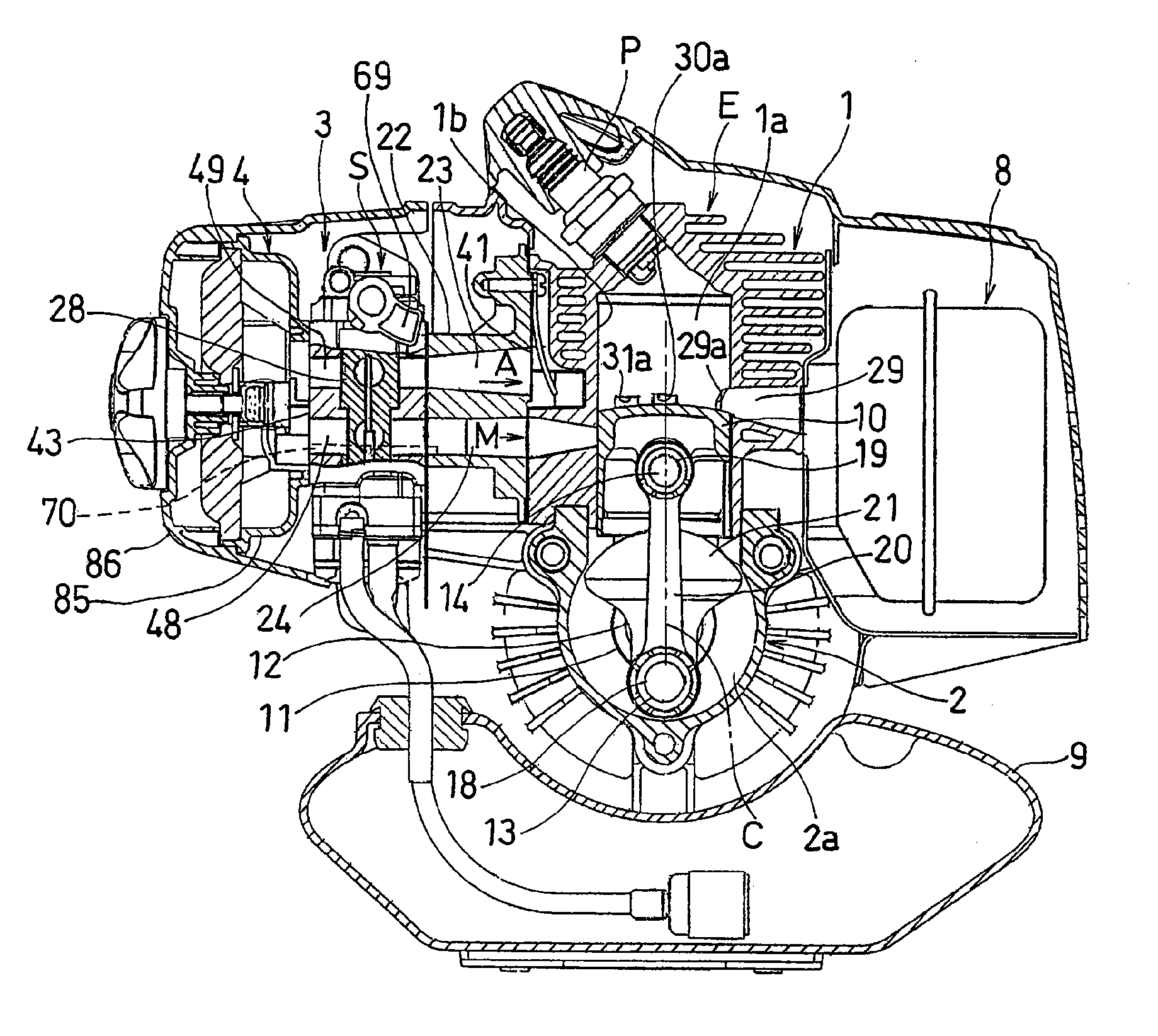
[0011]In view of the foregoing, the present invention is intended to provide a two-stroke cycle combustion engine of an air scavenging type, in which not only can transit from the idling condition to the rapid accelerating condition take place smoothly, but the combustion engine can be favorably started.
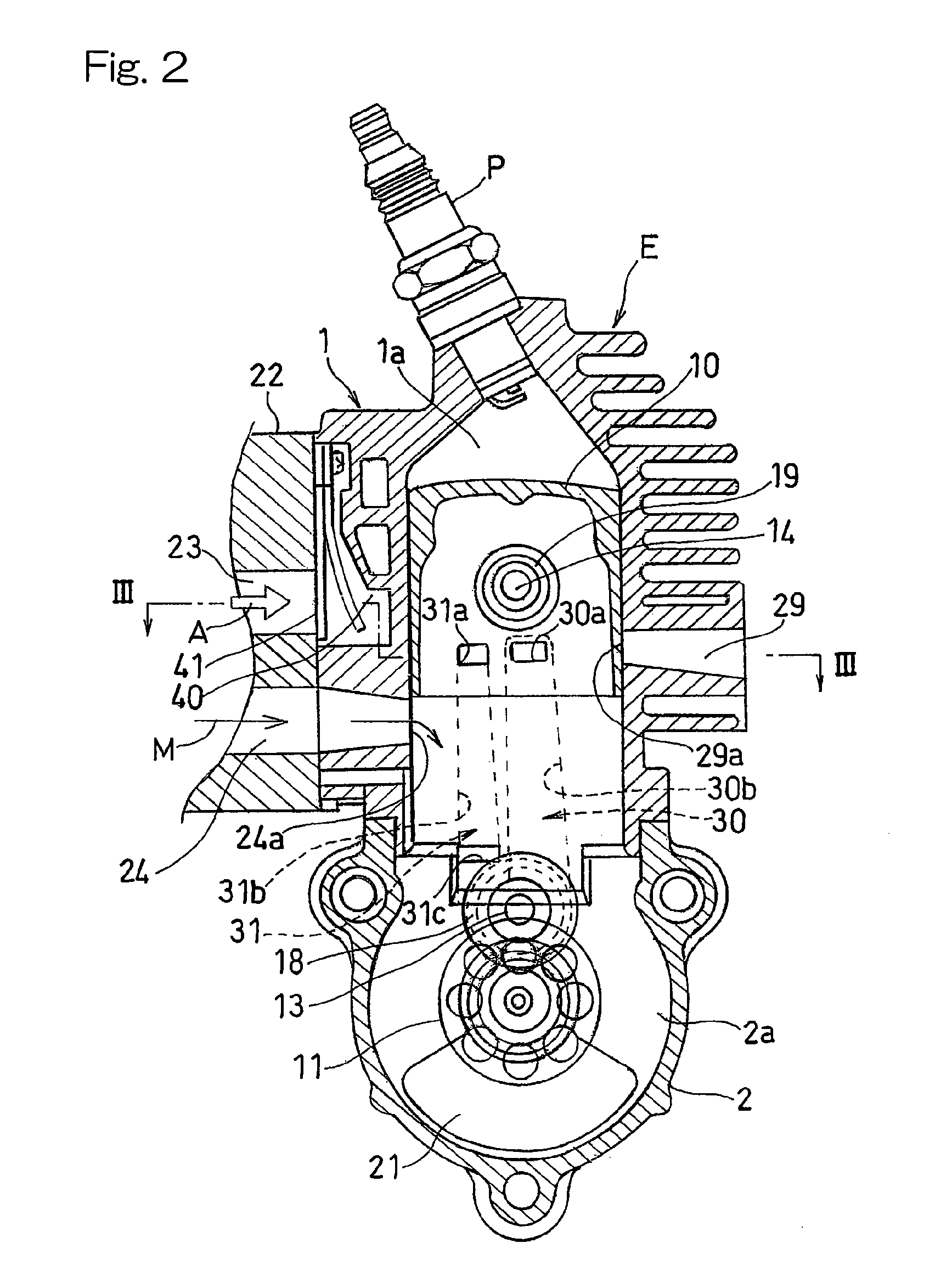
[0013]With the two-stroke cycle combustion engine according to the present invention, the auxiliary air flowing through the auxiliary air introducing passage can be introduced at a location downstream portion of the air / fuel mixture passage with respect to the direction of flow of the air / fuel mixture towards the combustion chamber. Therefore, the opening of the air / fuel mixture passage during the idling condition can be reduced to allow the air / fuel mixture to be enriched by, for example, adjusting a needle valve for setting the fuel flow in a quantity corresponding to the amount of the air so introduced during the idling condition. Since the amount of the air entering the combustion chamber is the sum of the air flowing through the air / fuel mixture passage and the air flowing through the auxiliary air introducing passage, the total amount of the air is increased. But if the amount of fuel is increased to a value required to achieve the number of idling revolutions about equal to that afforded by the conventional combustion engine, the air / fuel mixture within the combustion chamber will not be too enriched. Accordingly, at the time transit from the idling condition to the rapid acceleration is initiated, the air / fuel mixture pooled within the crank chamber during the idling condition can be supplied into the combustion chamber and, therefore, the combustion engine of the present invention can be accelerated rapidly. Also, since the throttle opening during the idling condition can be reduced as compared with that in the conventional combustion engine, the air passage will not be open large by the valve unit and, therefore, revolution of the combustion engine of the present invention can be stabilized.
[0014]Also, since the opening of the air / fuel mixture passage or the throttle opening can be reduced, a start operating mechanism, for example, of a lift-up type may be operated so that the lift-up amount is increased to enrich the air / fuel mixture thereby to improve the startability.
[0015]In a preferred embodiment of the present invention, the auxiliary air introducing passage may have a downstream portion defined in a spacer which is disposed between a carburetor, having the valve unit, and an engine body. This is particularly advantageous that since the downstream portion of the auxiliary air introducing passage is defined in the spacer having a plenty of available space as compared with the carburetor, positioning of the downstream of the auxiliary air passage can be facilitated.
[0016]In another preferred embodiment of the present invention, the auxiliary air introducing passage referred to above may have a throughhole defined in the carburetor for introducing a clean air, which has passed through an air cleaner, into the air / fuel mixture passage. This is particularly advantageous in that with no need to employ any extra member, and merely with the carburetor being modified or altered in any way whatsoever, the auxiliary air introducing passage can be readily formed.

Problems solved by technology

But if the amount of fuel is increased to a value required to achieve the number of idling revolutions about equal to that afforded by the conventional combustion engine, the air / fuel mixture within the combustion chamber will not be too enriched.

Method used


Image

  • Two-stroke cycle combustion engine of air scavenging type
  • Two-stroke cycle combustion engine of air scavenging type
  • Two-stroke cycle combustion engine of air scavenging type

Examples


second embodiment

[0067]In the second preferred embodiment of the present invention, the auxiliary air introducing passage 70A is made up of a delivery tube 78 fitted to a wall surface of the air cleaner 4 so as to extend therethrough with one end thereof positioned inside the clean air chamber 4a, an inflow tube 79 fitted to the insulator 22 so as to extend thereinto from outside, a connecting tube 80 connecting the delivery tube 78 with the delivery tube 79, and a communicating groove 81 defined in the insulator 22 for communicating the inflow tube 79 with the air / fuel mixture passage 24. Accordingly, in this second embodiment of the present invention, the auxiliary air introducing passage 70A can easily provided with no need to modify the carburetor 3 for this purpose.

[0068]FIG. 10 illustrates in a top sectional representation the combustion engine according to a third preferred embodiment of the present invention. It is to be noted that component parts shown in FIG. 9, but similar to those shown ...

third embodiment

[0070]Accordingly, even in this third embodiment, the auxiliary air introducing passage 70B can be provided with no need to modify the carburetor 3 for this purpose.

[0071]As discussed above, since the carburetor 3 employed in any of the embodiments shown in and described with particular reference to FIGS. 9 and 10, respectively, need not be modified or altered in anyway whatsoever as is the case with that in the second embodiment described previously, the versatility of the carburetor 3 can be expanded.

fourth embodiment

[0072]The two-stroke cycle combustion engine according to a fourth preferred embodiment of the present invention is shown fragmentarily in FIG. 11 in a front elevational representation. In the fourth embodiment, as the start operating mechanism, a standard choke mechanism is employed in place of the start lift up lever 69 shown in and described with particular reference to FIG. 1.

[0073]Referring now to FIG. 11, a choke valve CH is provided in the air cleaner 4. FIG. 12 illustrates a perspective representation showing the interior of the cleaner casing 85 of the air cleaner 4 and FIG. 13 illustrates a left side representation showing the cleaner casing 85. As best shown in FIG. 12, an air inflow hole 88 of a shape nearly similar to the shape of an hen egg is defined at a generally center portion of the cleaner casing 85, and an upper air delivery hole 89 and a lower air delivery hole 90 are defined in a portion of the cleaner casing 85 downstream of the air inflow hole 88 and positio...


PUM


Abstract

To provide a two-stroke cycle combustion engine of an air scavenging type, in which not only can transit from the idling condition to the rapid accelerating condition take place smoothly, but the combustion engine can be smoothly started, there are provided scavenging passages (30, 31) for introducing an air / fuel mixture (M) and an air (A) into a combustion chamber (1a), a valve unit (51, 50) for adjusting the opening of each of an air passage (23) for supplying the air (A) to the scavenging passage (30) and an air / fuel mixture passage (24) for supplying the air / fuel mixture (M) to the scavenging passage (31), and an auxiliary air introducing passage (70) for introducing an auxiliary air to the air / fuel mixture passage (24) at a location downstream of the valve unit (51, 50) in the air / fuel mixture passage (24).

Description

BACKGROUND OF THE INVENTION[0001]1. Field of the Invention[0002]The present invention relates to a two-stroke cycle combustion engine of an air scavenging type which may be used as a drive source for a portable work machine such as, for example, a brush cutter.[0003]2. Description of the Prior Art[0004]The two-stroke cycle combustion engine of a scavenging type has been well known, in which air used for leading scavenging is supplied into the combustion chamber after it has been temporarily introduced into a leading portion of the scavenging passage during the scavenging stroke. In this combustion engine, in order to secure a stabilized rotation during the idling condition, an air valve in the air passage is closed and only the air / fuel mixture is introduced into the crank chamber from an air / fuel mixture passage so that the air / fuel mixture of an optimum concentration can be supplied from the scavenging passage into the combustion chamber during the idling condition. On the other h...

Claims


Application Information

Patent Timeline
Patent Type & Authority Applications(United States)
IPC IPC(8): F02B25/00F02B23/00
CPCF02B25/14F02M35/1019F02B33/04F02B25/22
Inventor YUASA, TSUNEYOSHI
Owner KAWASAKI MOTORS LTD
Learn More