Driving support device, driving support method, and driving support program

a technology of driving support and support device, which is applied in the direction of vehicle position/course/altitude control, braking system, instruments, etc., can solve the problem that the related art is incapable of both decelerating the vehicle up to a certain targ

Active Publication Date: 2009-09-24
AISIN AW CO LTD
View PDF8 Cites 18 Cited by
  • Summary
  • Abstract
  • Description
  • Claims
  • Application Information

AI Technical Summary

Benefits of technology

[0013]In the present invention, the deceleration pattern selecting unit may select a deceleration pattern with a higher deceleration rate (larger absolute value) when the accelerator pedal is operated as compared to that selected when the accelerator pedal is not operated. This allows the deceleration control unit to delay the timing at which the speed reduction control intervenes and reliably achieve deceleration to the target vehicle speed, in order to reflect the driver's intent, as expressed by depressing the accelerator pedal, to the extent possible. Selecting a deceleration pattern with a higher rate of deceleration makes it possible to delay the timing at which the deceleration of the selected deceleration pattern is exceeded by the deceleration required to reduce the vehicle speed from that at the current location of the host vehicle to the target vehicle speed at the predetermined position. Delaying the timing at which the control intervenes means that a vehicle speed exceeding that of the deceleration pattern used as a reference is decelerated in a manner that resembles the deceleration pattern. As a consequence, deceleration can be achieved such that the target vehicle speed is reached at the predetermined position.

Problems solved by technology

However, the related art is incapable of both decelerating the vehicle up to a certain target point where deceleration should be completed and reflecting the driver's intent regarding the speed reduction control.

Method used


Image

  • Driving support device, driving support method, and driving support program
  • Driving support device, driving support method, and driving support program
  • Driving support device, driving support method, and driving support program

Examples


Embodiment Construction

[0024]Hereinafter, embodiments of the present invention will be described in the following order.[0025](1) Navigation Device Structure[0026](2) Driving Support Processing[0027](3) Other Embodiments

(1) Navigation Device Structure

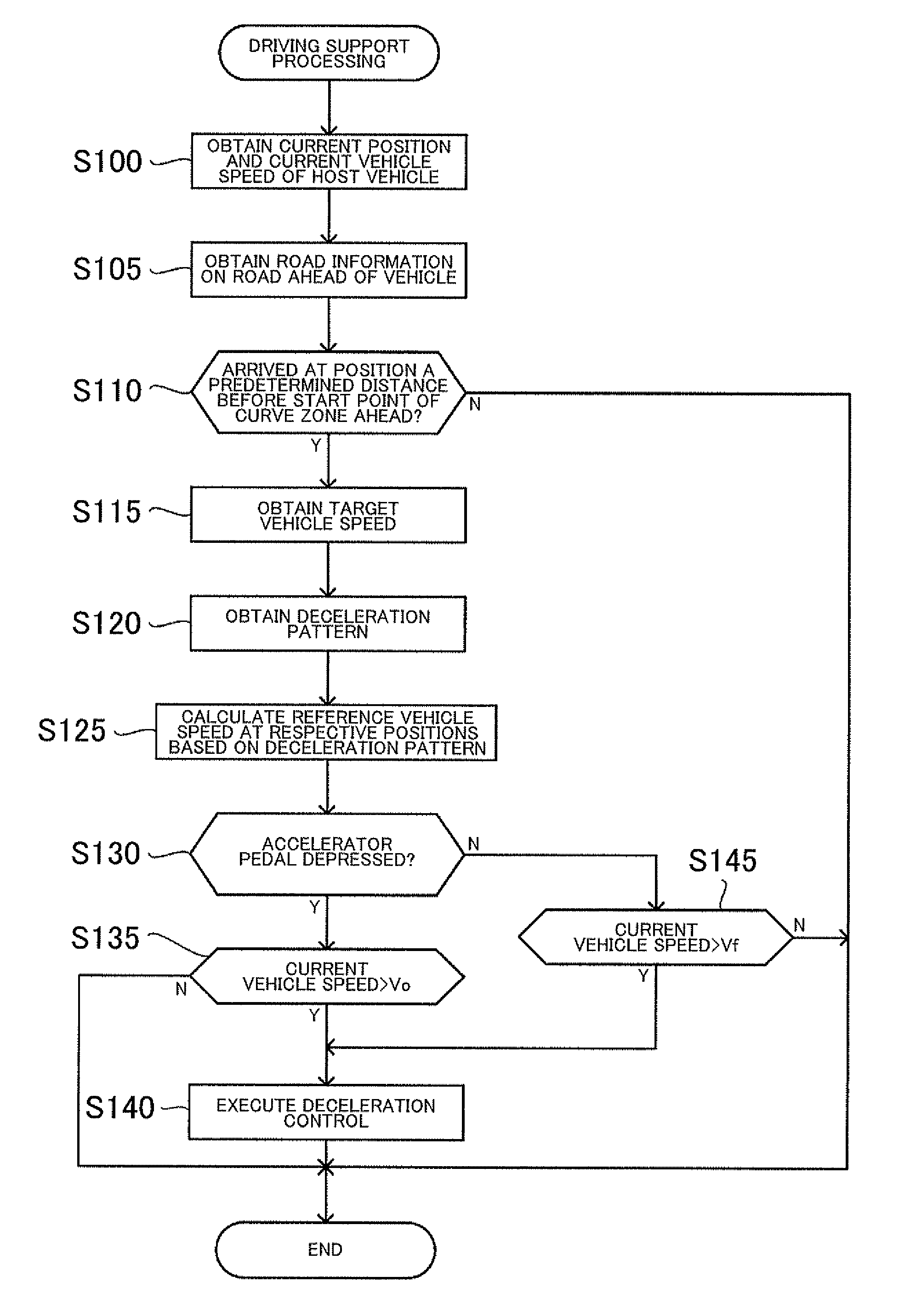
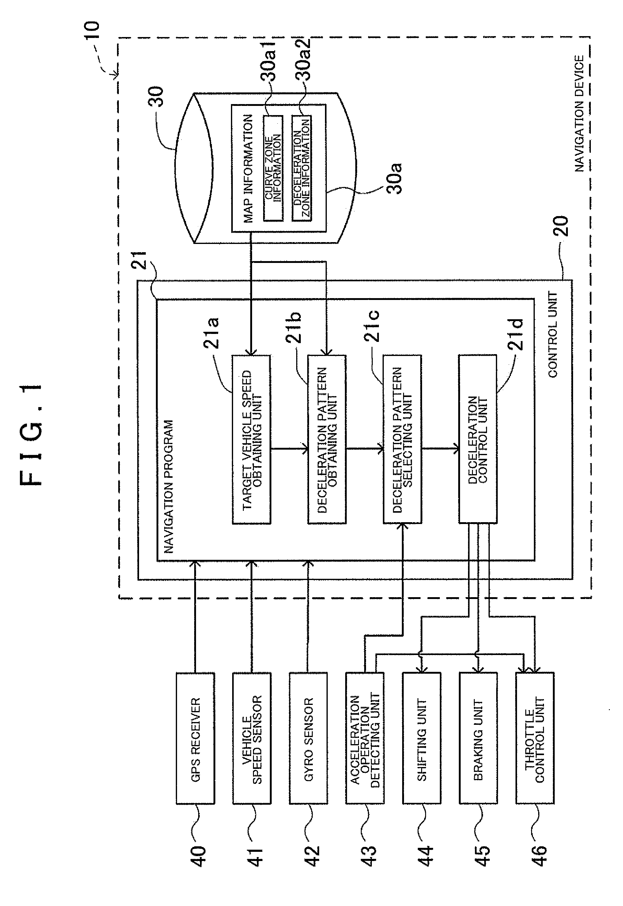
[0028]FIG. 1 is a block diagram showing the structure of a navigation device (apparatus) 10 incorporating a driving support device according to the present invention. The navigation device 10 includes a control unit 20 that has a CPU, a RAM, a ROM, and the like, and a memory medium 30. The navigation device 10 executes programs stored in the memory medium 30 and the ROM using the control unit 20. In the present embodiment, one such executable program is a navigation program 21, wherein the navigation program 21 functions to decelerate a host vehicle to reach a target vehicle speed at a predetermined position ahead of the host vehicle.

[0029]In order for the apparatus to realize functions in accordance with the navigation program 21, the host vehicle (a vehicle...


PUM


Abstract

A target vehicle speed at a predetermined position ahead of a host vehicle is obtained, and a plurality of deceleration patterns with different deceleration schemes is obtained for decelerating the host vehicle to the target vehicle speed. Based on a driving operation for controlling speed of the host vehicle, a deceleration pattern is selected from the plurality of deceleration patterns. Using the selected deceleration pattern as a reference, the vehicle speed of the host vehicle is reduced to the target vehicle speed before the host vehicle reaches the predetermined position.

Description

INCORPORATION BY REFERENCE[0001]The disclosure of Japanese Patent Application No. 2008-072822 filed on Mar. 21, 2008 including the specification, drawings and abstract is incorporated herein by reference in its entirety.BACKGROUND OF THE INVENTION[0002]1. Field of the Invention[0003]The present invention relates to a driving support device, a driving support method, and a computer-readable medium having, encoded thereon, a driving support program which perform a control that assists the driving of a vehicle.[0004]2. Description of the Related Art[0005]Systems for controlling speed of a vehicle using road information provided by a navigation device are known. Japanese Patent Application Publication No. JP-A-2004-116637 describes a control system that judges whether speed reduction control should be performed from a point in advance of a distance that is determined depending on the shape of a curve section ahead. If it is judged that a required speed is equal to or greater than a pred...

Claims


Application Information

Patent Timeline
Patent Type & Authority Applications(United States)
IPC IPC(8): G06F7/00B60T7/12B60W10/04B60W10/06B60W10/10B60W10/18B60W10/188B60W30/00B60W30/045F16H59/36F16H61/02F16H63/50
CPCB60W10/06B60W10/10B60W10/184B60W50/0098B60W2520/10B60W2720/106B60W2540/10B60W2540/30B60W2550/143B60W2550/402B60W2720/103B60W2520/14B60W30/18145B60W50/0097B60W2552/20B60W2552/30B60W2556/50
Inventor MIYAJIMA, TAKAYUKIOGAWA, FUMIHARUTAKEUCHI, ATSUSHIMARUYAMA, MASAKIKODAMA, HIROYUKIKOTO, HIDEAKI
Owner AISIN AW CO LTD
Why Eureka
Try Eureka