Wire-line core drilling hydraulic impactor

A hydraulic impactor and rope coring technology, which is used in the extraction of undisturbed core devices, earthwork drilling and other directions, can solve the problems of small contact area of ​​the seat ring, total growth, short life and other problems, and achieve structural strength and shock and vibration resistance performance. Enhanced, improved transfer efficiency, shortened drill assembly

Active Publication Date: 2011-08-17
昆明国经液压锤制造有限公司
View PDF9 Cites 13 Cited by
  • Summary
  • Abstract
  • Description
  • Claims
  • Application Information

AI Technical Summary

Problems solved by technology

The functional parts of the above-mentioned drilling tool are scattered, there are many parts in series, the mechanism is more complicated, the overall length is large, the ejection mechanism has many dynamic matching parts, the contact area of ​​the suspension ring and the seat ring is small, and it will be damaged quickly after long-term exposure to high-frequency shock and vibration. short

Method used


Image

  • Wire-line core drilling hydraulic impactor
  • Wire-line core drilling hydraulic impactor
  • Wire-line core drilling hydraulic impactor

Examples


Embodiment 1

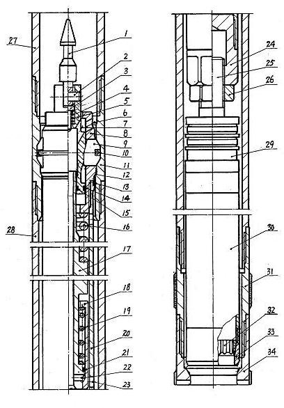
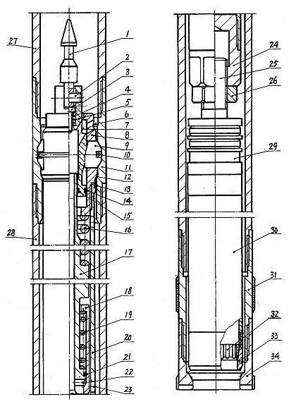
[0018] Such as figure 1 The rope coring hydraulic impactor shown has a throwing and fishing mechanism consisting of fishing spear head 1, threading pin 2, positioning pin 3, and positioning pin spring 4; wedging piston 5, positioning suspension seat 8, and positioning power transmission slider 9. Slider retraction spring 10, positioning suspension power transmission collar 11, sealing rings 13, 14, 15 form a hydraulic positioning suspension power transmission mechanism; hammer spring 16, hammer rod 17, sleeve valve 18, valve spring 19, shell 20 , sealing ring 21, anvil 24 constitute hydraulic impact mechanism.

[0019] The anvil 24 bottoms have screw holes to be connected with the connecting screw rod 25 on the single-action alarm mechanism 29 on the rope coring inner tube 30 top, after adjusting the gap between the spring seat 33 and the drill bit 34, lock it with the lock nut 26, and the outer tube 28 and the drill bit 34 are locked. A reamer 31 is installed between the dr...

Embodiment 2

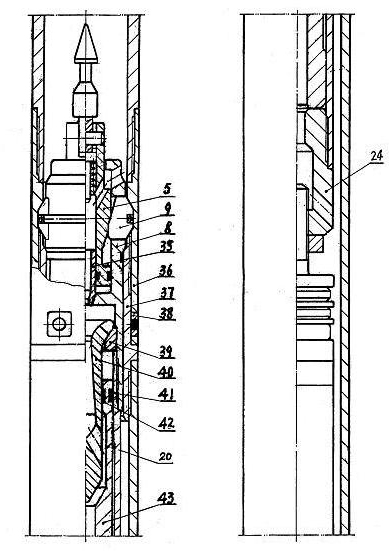
[0021] Such as figure 2 The shown rope coring hydraulic impactor is embodiment 2, which is different from embodiment 1 in that the hydraulic impact mechanism is composed of nozzle 35, valve travel seat 39, core valve 40, sealing rings 41, 42, housing 20, hammer body 43 and anvil 24, the nozzle 35 is installed in the wedging piston 5 for dynamic sealing fit, the valve travel seat 39 is fixed between the positioning suspension seat 8 and the shell 20, and the part below the valve crown of the core valve 40 passes through the valve travel seat 39 Inserted into the valve chamber on the upper part of the hammer body 43, the sealing rings 41 and 42 on the upper part of the hammer body 43 respectively cooperate with the positioning suspension seat 8 and the core valve 40 in dynamic sealing, and the two ends of the shell 20 are threadedly connected with the positioning suspension seat 8 and the anvil 24 respectively . When the drilling fluid passes through the nozzle 35, the hydraul...


PUM


Abstract

The invention relates to a wire-line core drilling hydraulic impactor which is used for impacting and rotary drilling in wire-line core drilling during core drilling; the impactor comprises a throwing and dragging mechanism, a hydraulic locating suspension power transmission mechanism and a hydraulic impacting mechanism; in the impactor, functions of throwing and dragging, location and suspension, impact vibration and impact power transmission are designed into a whole body, the structure is simplified, the drilling tool assembly is shortened, the structural design and the impact resistance vibration performance are strengthened; the location and locking between a locating power transmission sliding block and a locating suspension power transmission collar is combined in a pre-compaction state under the action of pressure generated by a ring-shaped conical surface in a hydraulic pushing wedging piston, and when the locating power transmission sliding block transmits impact power, the energy loss is little and the transmission efficiency is increased.

Description

technical field [0001] The invention relates to the field of drilling machinery, in particular to a percussion rotary drilling tool for core drilling by rope. Background technique [0002] The rope coring impact rotary drilling tool currently used in drilling production has a structure: the inner tube assembly is composed of a spear fishing mechanism, a cartridge positioning mechanism, an impact mechanism, a single-action alarm mechanism, an inner tube, a spring seat, and a spring. The outer tube assembly is composed of a bullet stopper, a bullet card chamber, an outer tube, a reamer, and a drill bit. The seat ring is borne, and some are also borne by the spline pair fixed on the outer tube assembly. The functional parts of the above-mentioned drilling tool are scattered, there are many parts in series, the mechanism is more complicated, the overall length is large, the ejection mechanism has many dynamic matching parts, the contact area of ​​the suspension ring and the sea...

Claims


Application Information

Patent Timeline
Patent Type & Authority Applications(China)
IPC IPC(8): E21B25/00
Inventor 刘国经
Owner 昆明国经液压锤制造有限公司
Why Eureka
Try Eureka