Bend pipe flow rate regulator
A regulator and elbow technology, applied in the direction of fluid flow, mechanical equipment, etc., can solve the problems affecting the flow resistance such as valve life, large asymmetrical impact force, and failure to overcome the regulator, etc., to improve life, large decomposition and Suppression, good effect of use
Inactive Publication Date: 2011-08-17
唐力南
View PDF4 Cites 2 Cited by
- Summary
- Abstract
- Description
- Claims
- Application Information
AI Technical Summary
Problems solved by technology
[0003] Through the above analysis, when the diameter of the pipe is large or the flow rate is high, the fluid will generate a very large asymmetric impact force after turning from the elbow pipe section, which will have a great impact on other flow resistance parts such as valves that follow it. Huge destructive impact, which seriously affects the life of choke parts such as valves
There is currently no regulator that overcomes the above drawbacks
Method used
View moreImage
Smart ImageViewing Examples

Examples
Embodiment Construction
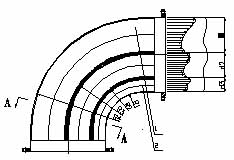
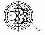
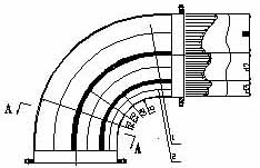
[0014] An elbow flow rate regulator, which includes an elbow 1 with a flange, such as figure 1 As shown: the above-mentioned elbow 1 is assembled sequentially from top to bottom by a series of adjustable stream elbows 2 with different diameters D and bending curvature R, as shown in figure 2 The ratio of the diameter of each flow stream elbow 2 shown in the figure to its corresponding curvature radius is equal or similar.
Login to View More PUM
 Abstract
The invention relates to a flow rate regulator, and in particular relates to a bend pipe flow rate regulator which comprises a bend pipe with a flange. The regulator provided by the invention is characterized in that the bend pipe is formed by sequentially assembling a series of flow rate regulating bend pipes with different diameters and different bend curvatures; and the ratio of the diameter of each flow rate regulating bend pipe to the curvature semi-diameter corresponding to the position of the flow rate regulating bend pipe is equal or approximate. The bend pipe flow rate regulator provided by the invention has the advantages that the structure is unique, centrifuge impact force is eliminated maximally, the flow rate of a fluid flows out of the bend pipe is distributed uniformly, the vibration of a regulating valve set is eliminated, and the service life of the device is prolonged.
Description
technical field [0001] The invention relates to a flow velocity regulator, in particular to an elbow flow velocity regulator. Background technique [0002] A flow conditioner is a device that eliminates abnormal flow and shortens the length of necessary straight pipe runs. There are many kinds of flow regulators currently available on the market, but all of them are designed and manufactured for partial rectification of straight pipes. Elbow is one of the blocking parts in the process pipeline. When the fluid flows through the elbow, it will produce "distortion of velocity distribution", "swirling flow" and "unsteady flow". In the pipe of the elbow, due to the turning of the fluid, there is a centrifugal force from the center of curvature to the outer wall of the pipe, which makes the pressure on the outer wall increase and the pressure on the inner wall decrease when the fluid transitions from the straight section of the pipe to the elbow section. Therefore, the flow velo...
Claims
Login to View More Application Information
Patent Timeline
 IPC IPC(8): F15D1/02
Inventor 唐力南
Owner 唐力南
Features
- R&D
- Intellectual Property
- Life Sciences
- Materials
- Tech Scout
- Unparalleled Data Quality
- Higher Quality Content
- 60% Fewer Hallucinations
Learn More Browse by: Latest US Patents, China's latest patents, Technical Efficacy Thesaurus, Application Domain, Technology Topic, Popular Technical Reports.
© 2025 PatSnap. All rights reserved.Legal|Privacy policy|Modern Slavery Act Transparency Statement|Sitemap|About US| Contact US: help@patsnap.com