
Light source circuit module with reflective structure, backlight module, and display

A circuit module and light source technology, applied in the direction of reflectors, electric light sources, refractors, etc., can solve the problems of uneven distribution of light intensity on the diffuser plate, poor display quality of LCD TVs, and uneven light intensity distribution, etc., to improve the backlight Uniformity, suppression of moiré phenomenon, high-quality color effects

Inactive Publication Date: 2011-08-17
AU OPTRONICS CORP
View PDF4 Cites 17 Cited by
  • Summary
  • Abstract
  • Description
  • Claims
  • Application Information

AI Technical Summary

Problems solved by technology

Although the reduction of the thickness of the diffusion plate will affect the light mixing effect, the shortening of the distance between the LED and the diffusion plate has a greater impact, resulting in a rather uneven distribution of light intensity entering the diffusion plate, which makes the effect of the diffusion plate to improve the light distribution limited. The most common The biggest problem is that LCD TVs produce moiré (mura), which makes the display quality of LCD TVs poor.
[0005] To solve this problem, although there are currently backlight modules coated with reflective materials on the circuit board, the light can be reflected even in places where there is no light source, so as to improve the problem of uneven distribution of light intensity entering the diffuser plate.
Although this method can improve the phenomenon of moiré, since the reflectivity of each part of the circuit board is fixed, and the intensity of light reaching all parts of the circuit board decreases with the increase of the distance between the circuit board and the light source, the light reflected from all parts of the circuit board The intensity also decreases with the increase of the distance from the light source, so the overall intensity of the light reflected by the circuit board farther away from the light source is still weaker, so that the overall light distribution is still concentrated, and the phenomenon of moiré remains the same. Exist, limited improvement effect

Method used


Image

  • Light source circuit module with reflective structure, backlight module, and display
  • Light source circuit module with reflective structure, backlight module, and display
  • Light source circuit module with reflective structure, backlight module, and display

Examples


Embodiment Construction

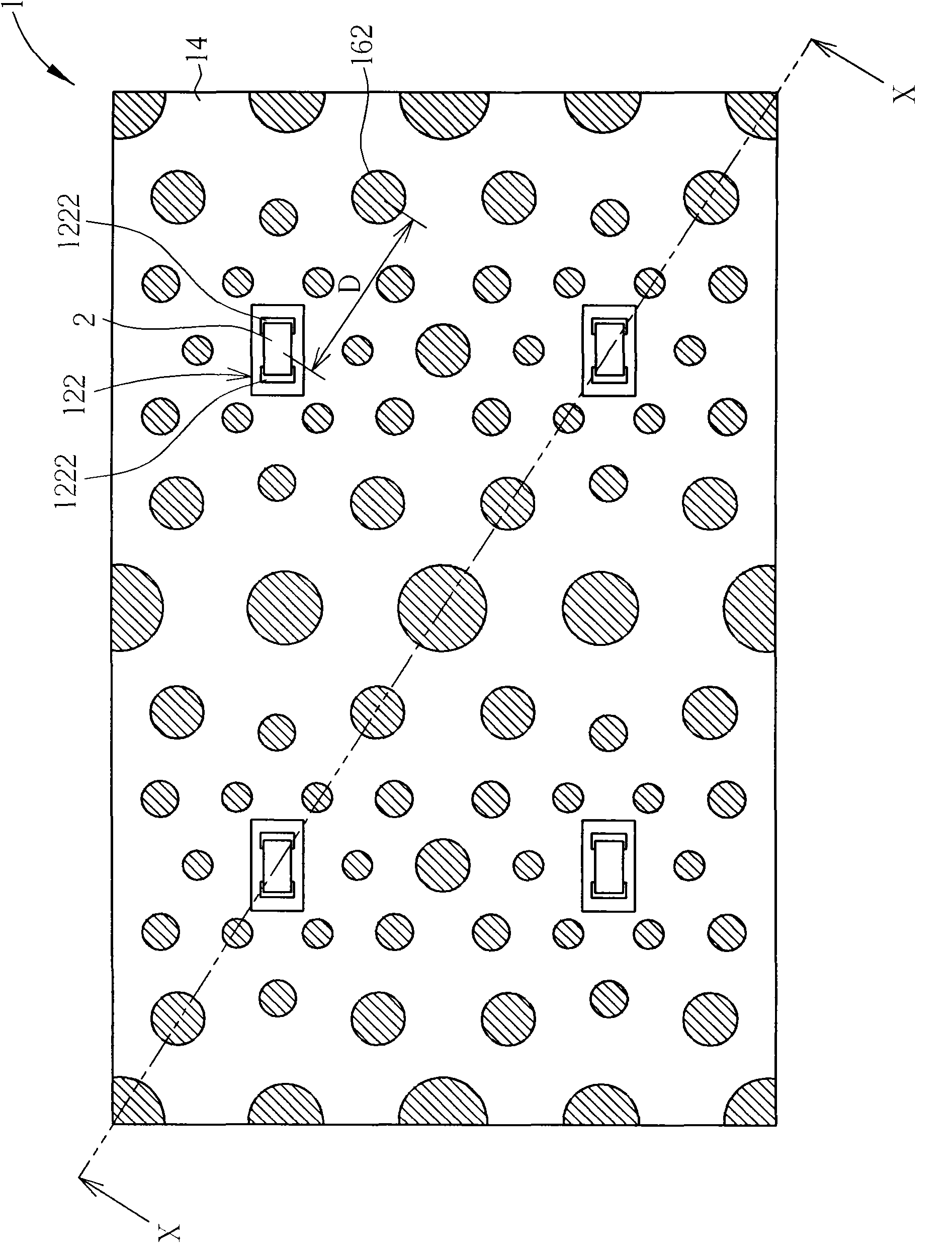
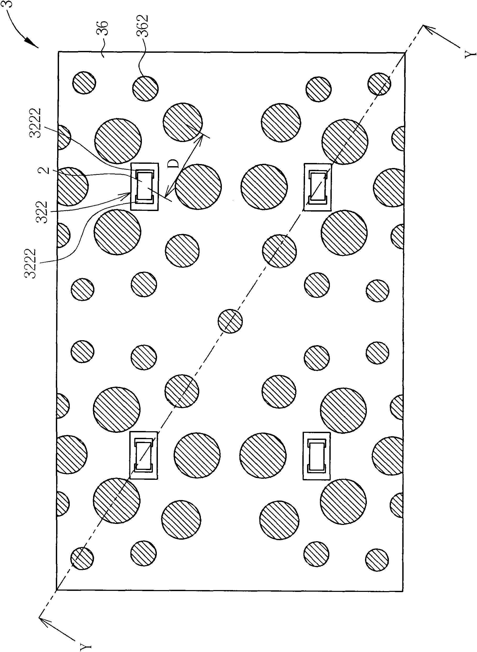
[0033] Please refer to figure 1 and figure 2 , figure 1 It is a top view of a light source circuit module 1 according to a first preferred embodiment of the present invention, figure 2 for figure 1A cross-sectional view of the middle light source circuit module 1 along the secant line X-X. The light source circuit module 1 includes a circuit board 12 , a first reflective layer 14 and a second reflective layer 16 . The circuit board 12 includes a plurality of electrical connection areas 122 (indicated by boxes), and each electrical connection area 122 may include two electrode pads 1222 on which a light emitting diode 2 is electrically connected and fixed. The first reflective layer 14 is formed on a surface 124 of the circuit board 12 and has a first reflectivity R1. The second reflective layer 16 is formed on the first reflective layer 14 to partially cover the first reflective layer 14 and has a second reflectivity R2 greater than the first reflectivity R1. The secon...


PUM


Abstract

The invention discloses a light source circuit module with a reflective structure, and a backlight module and a display employing the same. The light source circuit module comprises a circuit board, a first reflective layer and a second reflective layer, wherein the first reflective layer is formed on the surface of the circuit board and has a first reflectivity, and the second reflective layer is formed on and partially covers the first reflective layer and has a second reflectivity higher than the first reflectivity. The overlapping area of the second reflective layer over the first reflective layer can be adjusted so as to adjust the reflectivity of the reflective structure formed by the first reflective layer and the second reflective layer, and to improve the uniformity of the light supplied by the light source circuit module, thereby solving the problem of graduated shade of the prior art due to nonuniform light supplied by a light source.

Description

technical field [0001] The invention relates to a light source circuit module, a backlight module and a display with the light source circuit module, in particular to a light source circuit module, a backlight module and a display with a light reflection structure. Background technique [0002] With the rapid development of liquid crystal display (Liquid Crystal Display, LCD) manufacturing technology, it has the advantages of light and thin, power saving and no radiation, so that liquid crystal display is widely used in various electronic devices with display requirements, such as personal digital Assistant (Personal Digital Assistant, PDA), notebook computer, digital camera, digital video recorder, computer screen and LCD TV, etc. Since the liquid crystal display panel in the liquid crystal display device is a non-self-illuminating display panel, it needs the light provided by the backlight module to produce the function of displaying images. [0003] With the improvement ...

Claims


Application Information

Patent Timeline
Patent Type & Authority Applications(China)
IPC IPC(8): F21S8/00F21V5/08F21V7/22F21V23/06G09F9/30
Inventor 王炯翰廖述珀
Owner AU OPTRONICS CORP
Learn More