Equipment monitoring and diagnosing method

A technology of equipment and eigenvalues, which is applied in the field of monitoring and diagnosis at a fixed speed of the equipment, can solve the problems of affecting practicability and replication, over-learning sample explosion, and reducing application effectiveness, so as to achieve the effect of reducing scale and difficulty

Inactive Publication Date: 2011-08-17
CHINA STEEL
View PDF6 Cites 17 Cited by
  • Summary
  • Abstract
  • Description
  • Claims
  • Application Information

AI Technical Summary

Problems solved by technology

[0007] However, in actual application, the following factors affect its practicability and replication to other devices, so the application effect is reduced
[0008] The best normalized problem: the input value and expected value of the neural network, in order to cooperate with the nonlinear function in the calculation process, need to be normalized to [0, 1] or [-1, 1], the size of the normalization will affect the sensitivity of the identification system, so there is an optimal regularization problem
[0011] How to represent the evolution process of trend analysis in the identification process? If the neural network is based on the input value (eigenvalue after digital signal processing) and its related frequency, it can distinguish whether the equipment has (simultaneous or single) fault conditions such as imbalance, eccentricity, or bearing damage under good regularization conditions. , but using this method will encounter great difficulties in failure trend analysis, that is, under the same eigenfrequency, the eigenvalue increases with the increase of the failure trend. Once it increases to a certain value, it may be due to the change of the cluster center , and another new fault type is issued, but it should be regarded as the same fault type rather than a new fault generation, the difference between them is only in the degree, so in such a learning process, there is over-learning and sample explosion question
[0012] As mentioned above, when the above-mentioned existing problems of fault monitoring and analysis technology in practical application cannot be overcome, let alone how to use this technology to assist equipment management

Method used


Image

  • Equipment monitoring and diagnosing method
  • Equipment monitoring and diagnosing method
  • Equipment monitoring and diagnosing method

Examples


Embodiment Construction

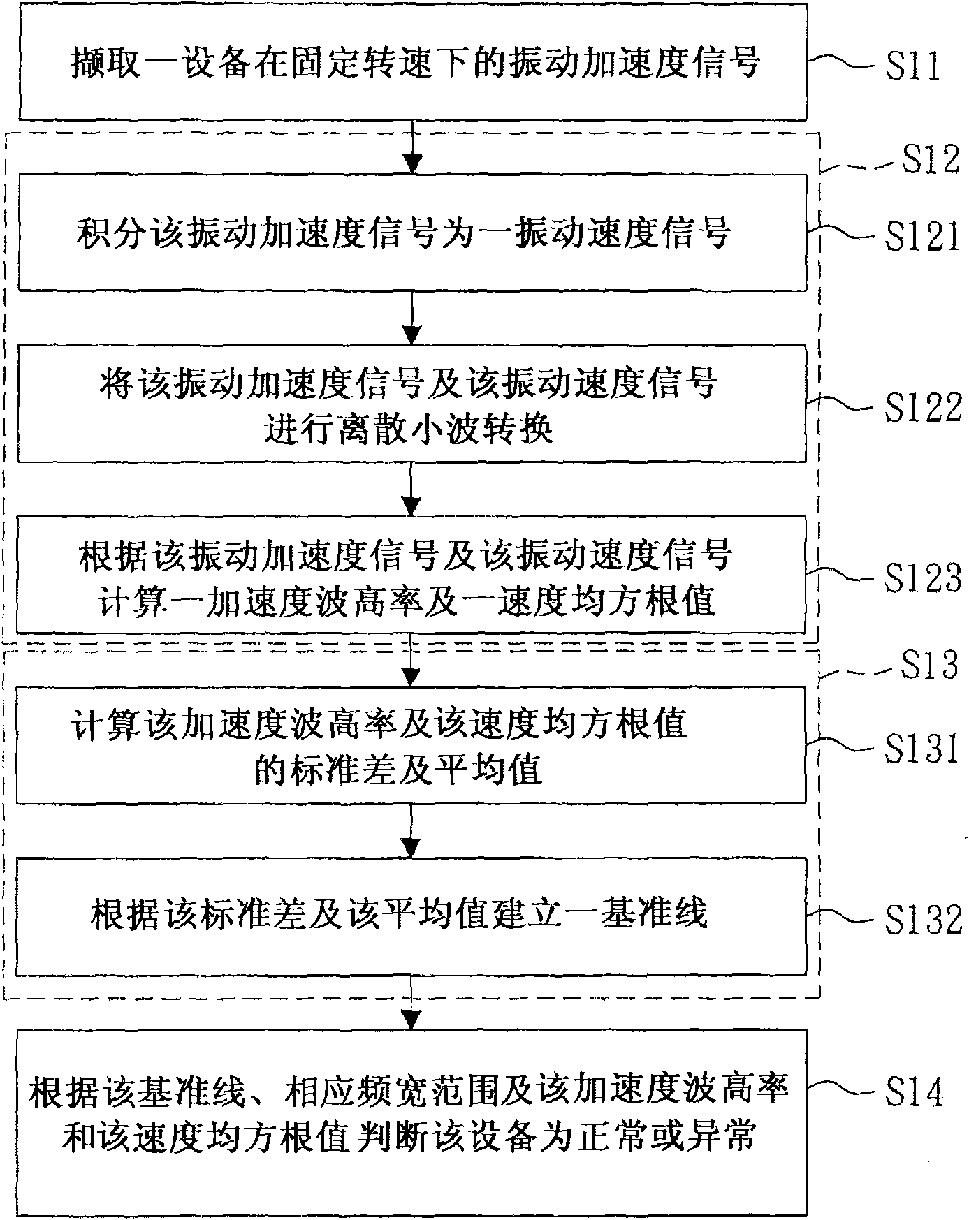
[0028] refer to figure 1 , which shows the flowchart of the device monitoring method of the present invention. The equipment monitoring and diagnosis method of the present invention is used for abnormal detection of an equipment, and the equipment can operate at a fixed speed. Firstly, referring to step S11, a vibration signal of the device at the fixed rotational speed is captured, wherein the frequency of the vibration signal has multiple frequency ranges.

[0029] In this embodiment, the method of the present invention continuously acquires a vibration acceleration signal of the device at the fixed rotational speed. Wherein, in step S11, a vibration sensor can be used to capture the vibration acceleration signal under the setting of fixed high-pass filter and low-pass filter cut-off frequency. Preferably, the cut-off frequency of the high-pass filter is set at 0.5 Hz, the cut-off frequency of the low-pass filter is set at 3000 Hz, and the vibration acceleration signal is ...


PUM


Abstract

The invention provides an equipment monitoring and diagnosing method, comprising the following steps of obtaining a vibration signal of the equipment under a fixed rotation speed; calculating the characteristic value complying with Gaussian distribution within the corresponding frequency width range according to the vibration signal so as to establish at least one benchmark line; subsequently judging the normality or abnormality of the equipment according to the benchmark line, the corresponding frequency width range and the characteristic value; therefore, if the vibration signal exceeds the benchmark line of safe range, the abnormality and failure type can be diagnosed and recognized; and furthermore, the aim of owning the automatic monitoring and diagnosing and learning capabilities can be realized. Furthermore, the equipment monitoring and diagnosing method does not need to consider all failure types that may occur in the whole service life of the equipment so as to greatly reduce the development scale and difficulty of the failure monitoring and diagnosing system, thus improving the visualization of the equipment condition and increasing the completion rate of the equipment.

Description

technical field [0001] The present invention relates to a method for monitoring and diagnosing equipment, in particular, relates to a method for monitoring and diagnosing equipment at a constant rotational speed. Background technique [0002] Equipment fault monitoring is developed for the effective implementation of equipment maintenance and management. In the development process of the existing fault monitoring technology, the focus of the analysis process is a top-down approach. Among them, the analysis process with vibration as the monitoring object is roughly vibration signal extraction, digital signal processing, signal feature extraction and decision analysis. [0003] In this existing fault monitoring process, it is faced with the problem of many choices. First of all, according to the operating conditions of the monitoring equipment, should you choose to measure acceleration, velocity or displacement amplitude signals? The signal selection part will determine the...

Claims


Application Information

Patent Timeline
Patent Type & Authority Applications(China)
IPC IPC(8): G01H17/00
Inventor 王智中吴崇勇柯忠和林智贤李仙家刘熙铭
Owner CHINA STEEL
Why Eureka
Try Eureka