
Three-dimensional adjustable laser transmitting device of anti-collision radar system

An anti-collision radar and laser emission technology, applied in the field of vehicle anti-collision radar, can solve the problems of inattention, illegal operation of novice drivers, improper operation, etc., and achieve the effects of three-dimensional adjustment, convenient beam adjustment, and reliable structure

Inactive Publication Date: 2011-08-17
王小刚 +1
View PDF6 Cites 5 Cited by
  • Summary
  • Abstract
  • Description
  • Claims
  • Application Information

AI Technical Summary

Problems solved by technology

[0002] With the development of society, the number of cars is gradually increasing, and the traffic accidents that follow are also increasing year by year. Most of them are accidents caused by rear-end collisions or collisions with obstacles due to untimely braking. The specific situations are: drivers When the attention is not concentrated or disturbed, when a sudden accident occurs in front of the car, it is too late to brake; the road is slippery in rainy days, and the driver's inaccurate grasp of the speed and distance leads to rear-end collision accidents; drunk driving, improper operation causes accidents; Accidents caused by personnel not responding quickly enough or novice drivers operating illegally

Method used


Image

  • Three-dimensional adjustable laser transmitting device of anti-collision radar system
  • Three-dimensional adjustable laser transmitting device of anti-collision radar system
  • Three-dimensional adjustable laser transmitting device of anti-collision radar system

Examples


Embodiment Construction

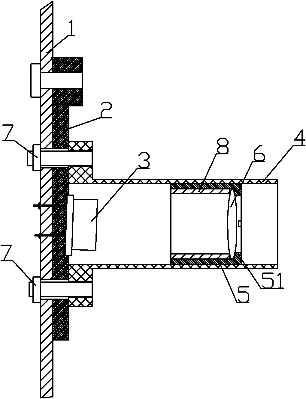
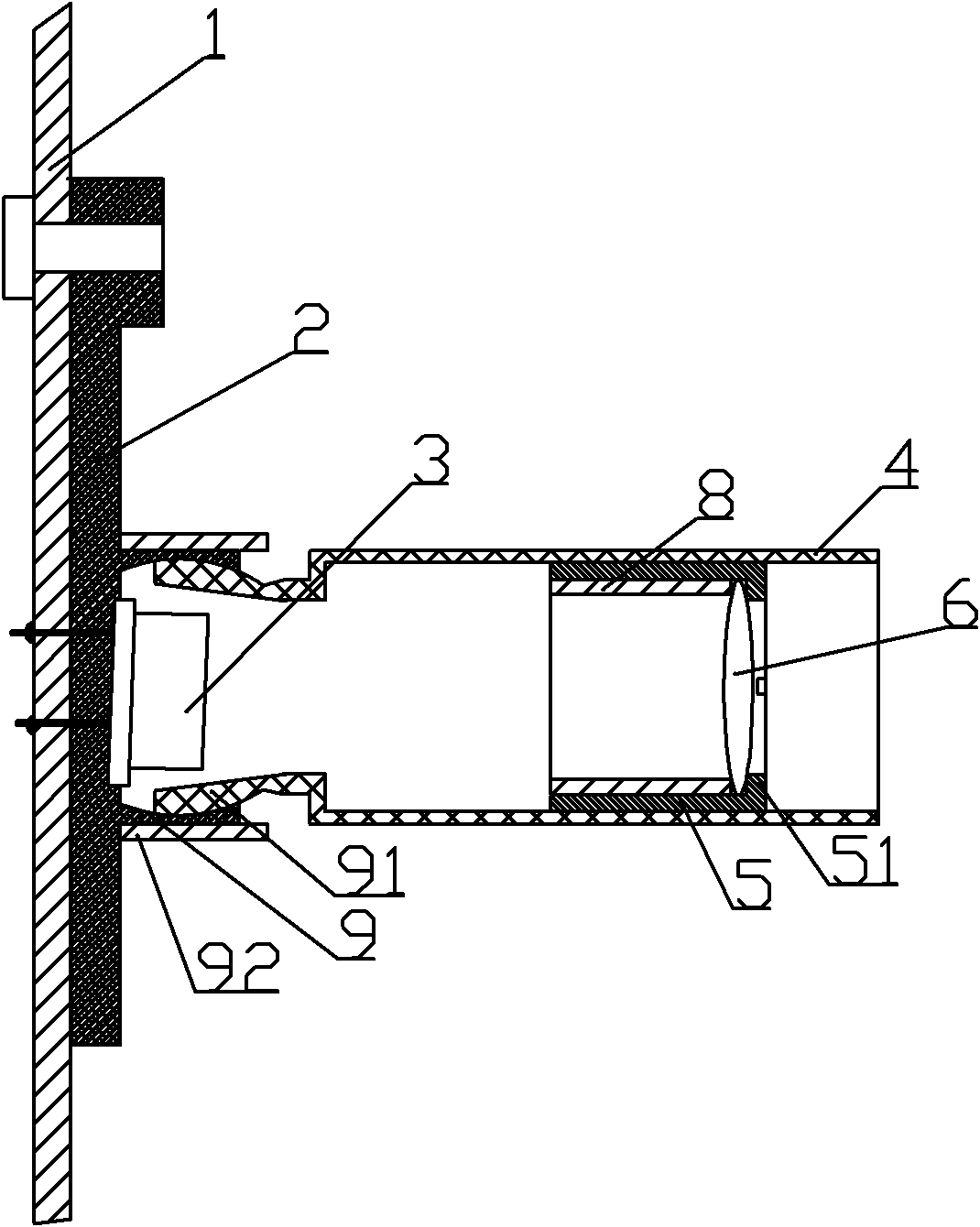
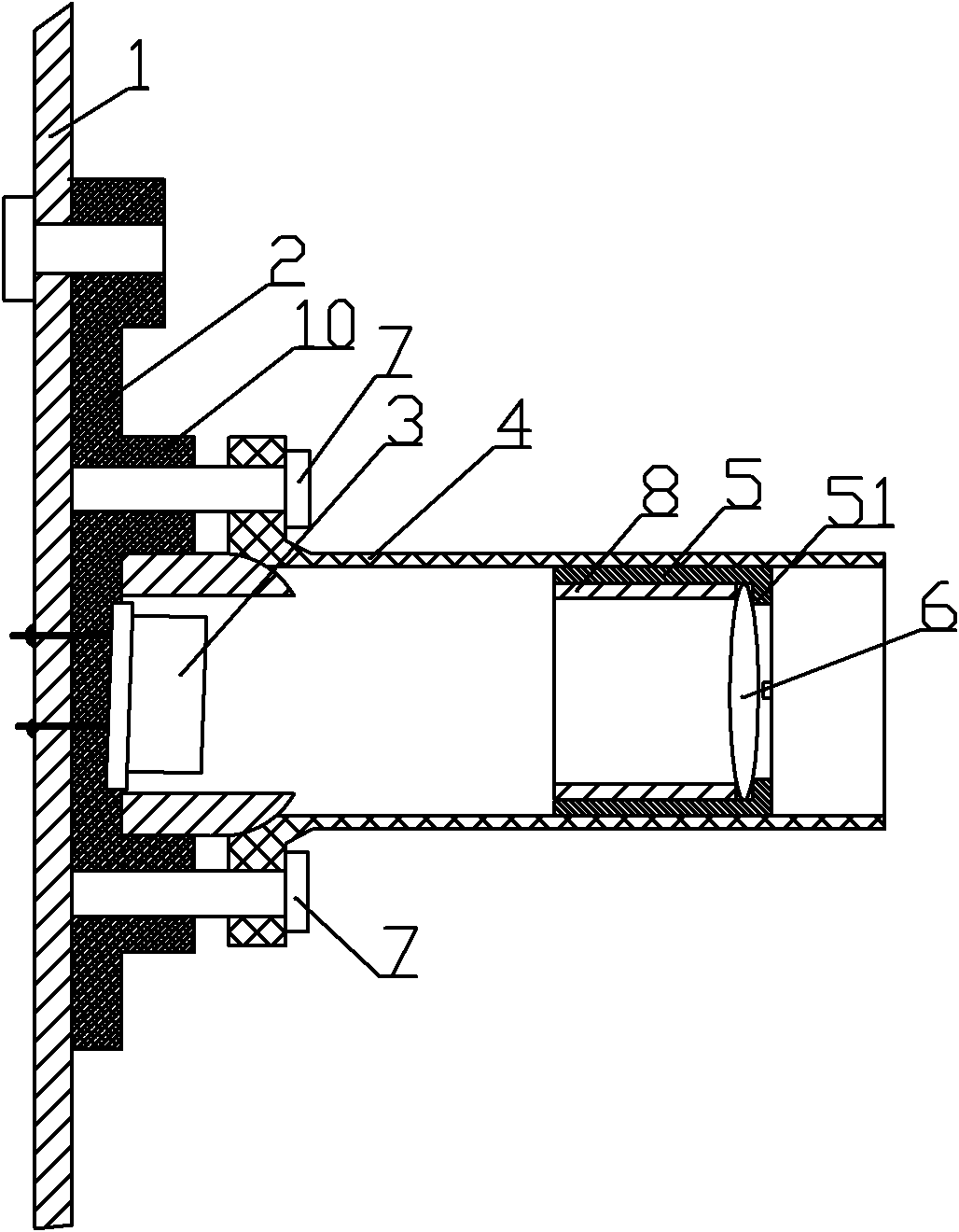
[0020] Such as figure 1 with 4 The transmission device a shown by the translation method of focusing includes a circuit board 1, a laser 3, a lens holder 4, a lens cover 5 and a lens 6, the laser 3 is welded on the circuit board 1, and the lens holder 4 is set on the laser 3 and The circuit board 1 is fixed by the adjustment screw 7, the lens 6 is installed in the lens cover 5, the outer ring of the lens cover 5 and the inner ring of the lens holder 4 have threads, the lens cover 5 is screwed into the lens holder 4 to adjust the focal length, and the adjustment screw 7 is threaded. The circuit board 1 and the insulating backing plate 2 are connected to the lens mount 4, and the screw holes on the circuit board 1 and the insulating backing plate 2 are larger than the diameter of the adjusting screw 7. An insulating backing plate 2 is arranged between the laser 3 and the circuit board 1, and the bottom of the laser 3 is installed close to the insulating backing plate 2. The con...


PUM


Abstract

The invention relates to a three-dimensional adjustable laser transmitting device of an anti-collision radar system. A laser is welded on a circuit board; a lens holder is sleeved on the laser and fixed with the circuit board through an adjusting screw; a lens sleeve is screwed in the lens holder to adjust a focal distance; the diameter of a screw hole on the circuit board through which the adjusting screw passes is greater than the diameter of the adjusting screw; and an emitted light beam is accordant with required orientation by translation of the lens holder. Or an opening ball socket is formed on an insulating base plate; a ball head is arranged on the lens holder; the ball head of the lens holder is embedded into the opening ball socket; and the orientation of the light beam is adjusted by a ball head method. Or the lens holder is pressed against an adjusting seat and fixed on the circuit board through the adjusting screw; contact surfaces of the adjusting seat and the lens holder are internal and external spherical cambered surfaces; and the orientation of the light beam is adjusted by a cambered surface method. A receiving device is reliable and compact in structure and realizes installation of a plurality of lasers in a limited space of the circuit board; and the light beam is adjusted conveniently, so that the three-dimensional adjustment of the light beam can be realized.

Description

technical field [0001] The invention relates to a vehicle anti-collision radar, in particular to a three-dimensional adjustable laser emitting device of the anti-collision radar system. Background technique [0002] With the development of society, the number of cars is gradually increasing, and the traffic accidents that follow are also increasing year by year. Most of them are accidents caused by rear-end collisions or collisions with obstacles due to untimely braking. The specific situations are: drivers When the attention is not concentrated or disturbed, when a sudden accident occurs in front of the car, it is too late to brake; the road is slippery in rainy days, and the driver's inaccurate grasp of the speed and distance leads to rear-end collision accidents; drunk driving, improper operation causes accidents; Accidents caused by personnel not responding quickly enough or novice drivers operating illegally. The human reaction cannot keep up with that of the machine. ...

Claims


Application Information

Patent Timeline
Patent Type & Authority Applications(China)
IPC IPC(8): G01S7/481
Inventor 王小强王小刚
Owner 王小刚
Learn More