Electromechanical rotor

A rotor and electromechanical technology, applied in the manufacture of stator/rotor body, magnetic circuit rotating parts, shape/style/structure of winding insulation, etc., can solve the problem of poor sealing between end plates and insulating shafts, greater influence of environmental factors, Increase the work process and other issues to achieve the effect of reducing procedures, reducing costs and improving friction

Inactive Publication Date: 2011-08-17
KANGPING TECH SUZHOU CO LTD
View PDF3 Cites 6 Cited by
  • Summary
  • Abstract
  • Description
  • Claims
  • Application Information

AI Technical Summary

Problems solved by technology

The disadvantage of the existing electromechanical rotor is that the end plate and the insulating bushing are set separately, so two processes are required to attach the end plate and the insulating bushing to the rotating shaft and the rotor core when making the electromechanical rotor, which increases the The working process reduces the working efficiency, and the sealing performance of the separately designed end plate and the connection of the insulating shaft is poor
In addition, the existing end plate is made of red steel paper. This kind of red steel paper has strong water absorption, is greatly affected by environmental factors, and is easy to cause deformation. During the production process of the motor, it often causes paper or line pressing.

Method used


Image

  • Electromechanical rotor
  • Electromechanical rotor
  • Electromechanical rotor

Examples


Embodiment Construction

[0016] The specific implementation manners of the present invention will be further described in detail below in conjunction with the accompanying drawings and embodiments. The following examples are used to illustrate the present invention, but are not intended to limit the scope of the present invention.

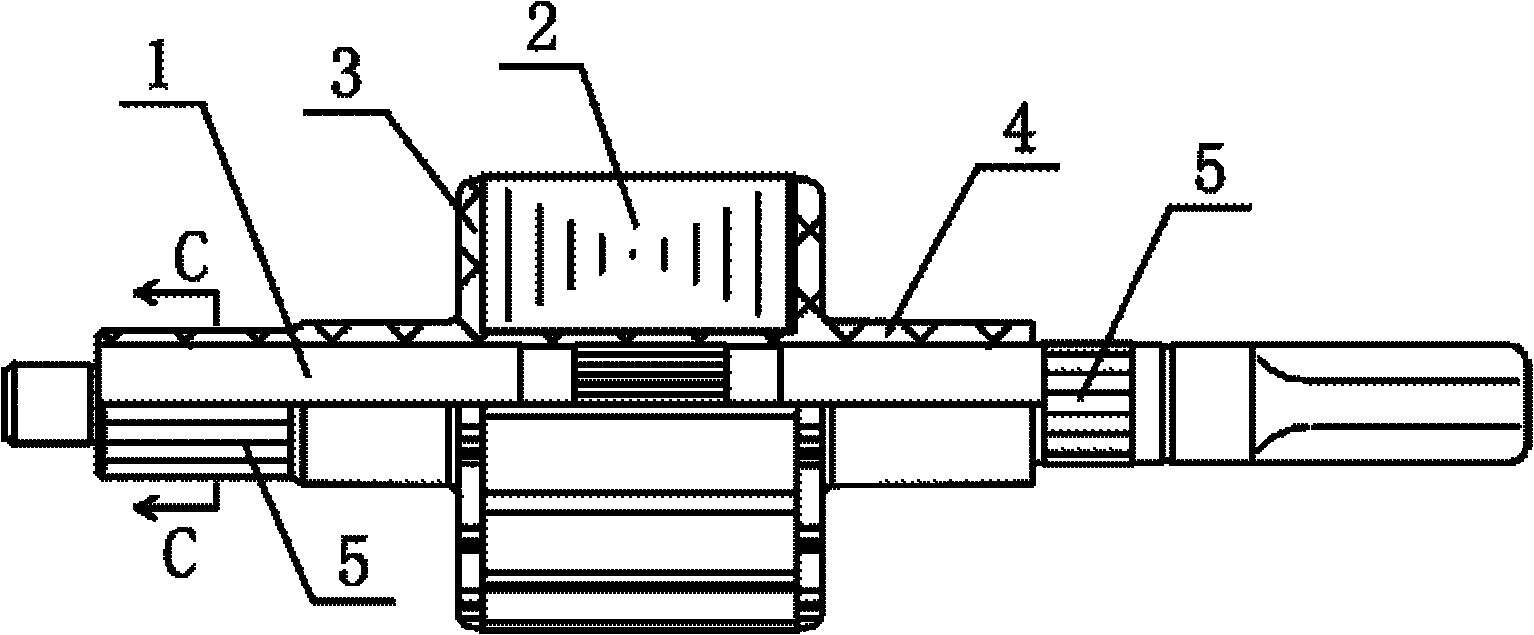
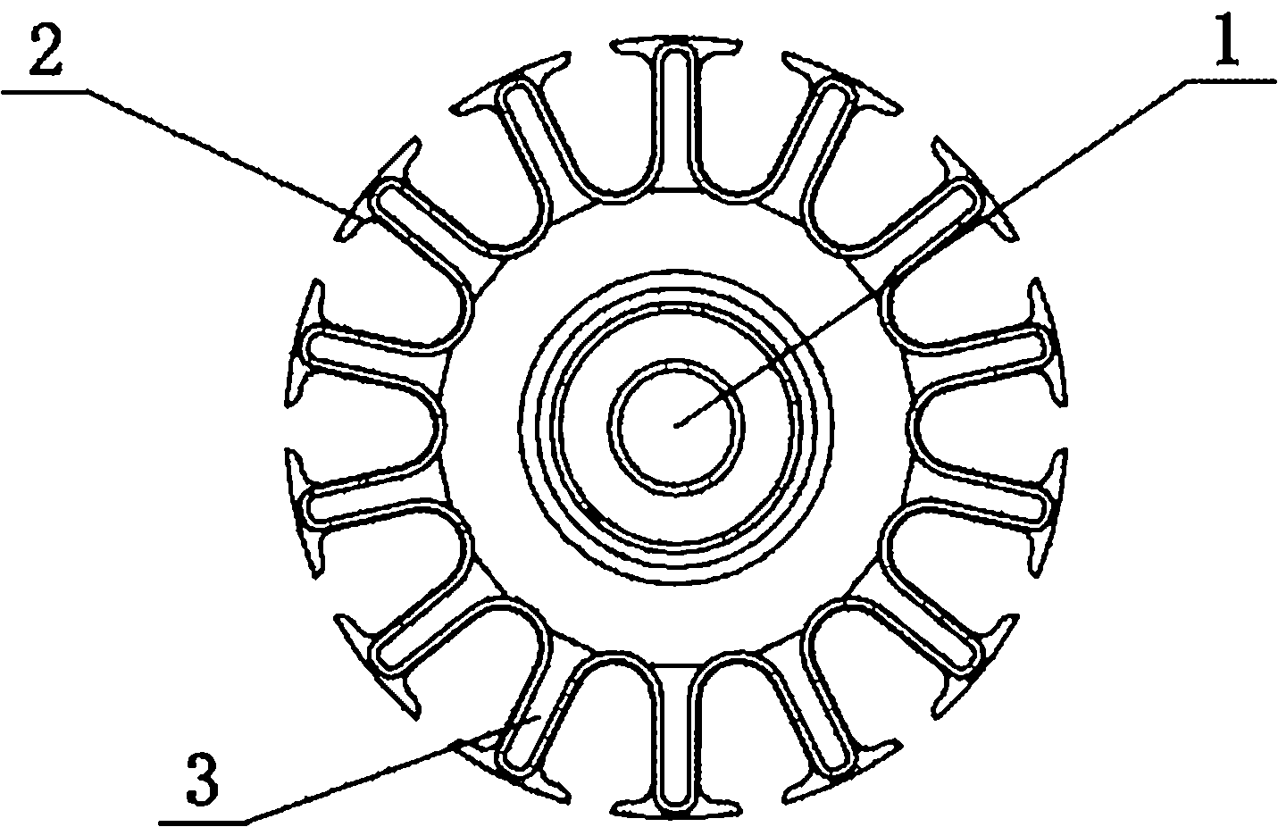
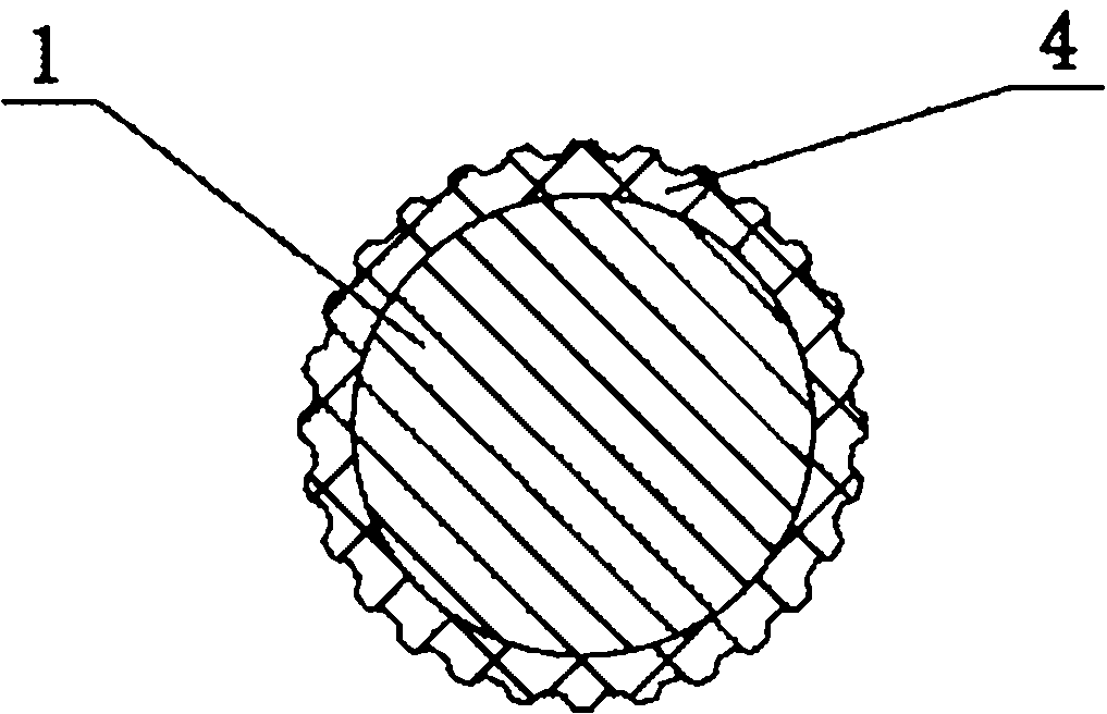
[0017] Such as figure 1 , figure 2 and image 3 As shown, an electromechanical rotor includes a rotating shaft 1, a rotor core 2, an end plate 3 made of BMC material and an insulating bushing 4 made of BMC material, and the insulating bushing 4 made of BMC material is attached to the rotating shaft 1 , the rotor core 2 is set on the rotating shaft 1 and connected to the rotating shaft 1 through the insulating sleeve 4 attached to the rotating shaft 1, and the insulating sleeves 4 on the left and right sides of the rotor core 2 are evenly provided with protrusions 5, the protrusions 5 It can improve the friction force and enhance the torque of the electronic rotor; the ...


PUM


Abstract

The invention discloses an electromechanical rotor which comprises a rotating shaft, a rotor iron core, end plates and an insulating shaft sleeve, wherein the insulating shaft sleeve is clung on the rotating shaft, the rotor iron core is sleeved on the rotating shaft and is connected with the rotating shaft through the insulating shaft sleeve clung on the rotating shaft, the end plates are clung on two sides of the rotor iron core, and the insulating shaft sleeve and the end plates are integrated into a one body. In the electromechanical rotor, since the insulating shaft sleeve and the end plates are integrated into a one body, one processing step is omitted during the manufacturing of the electromechanical rotor, thereby saving time and reducing cost.

Description

technical field [0001] The invention relates to the field of motor accessories, in particular to an electromechanical rotor. Background technique [0002] The existing electromechanical rotor includes a rotating shaft, a rotor core, an end plate and an insulating sleeve. The insulating sleeve is attached to the rotating shaft. The rotor core is sleeved on the rotating shaft and connected to the rotating shaft through the insulating sleeve attached to the rotating shaft. The end plate It is attached to both sides of the rotor core and connected to the insulating sleeve attached to the rotating shaft. The disadvantage of the existing electromechanical rotor is that the end plate and the insulating bushing are set separately, so two processes are required to attach the end plate and the insulating bushing to the rotating shaft and the rotor core when making the electromechanical rotor, which increases the In the working process, the work efficiency is reduced, and the sealing ...

Claims


Application Information

Patent Timeline
Patent Type & Authority Applications(China)
IPC IPC(8): H02K1/22H02K3/38H02K15/02
Inventor 夏威夏宇华陈颖颖
Owner KANGPING TECH SUZHOU CO LTD
Why Eureka
Try Eureka