Servo test device and method for performance of optical signal emitted by satellite optical communication terminal
A satellite optical communication and test device technology, applied in the field of aviation applications, can solve the problems of inability to realize follow-up control and large size of the test device, and achieve the effects of light weight, convenient remote measurement, and improved integrity
- Summary
- Abstract
- Description
- Claims
- Application Information
AI Technical Summary
Problems solved by technology
Method used
Image
Examples
specific Embodiment approach 1
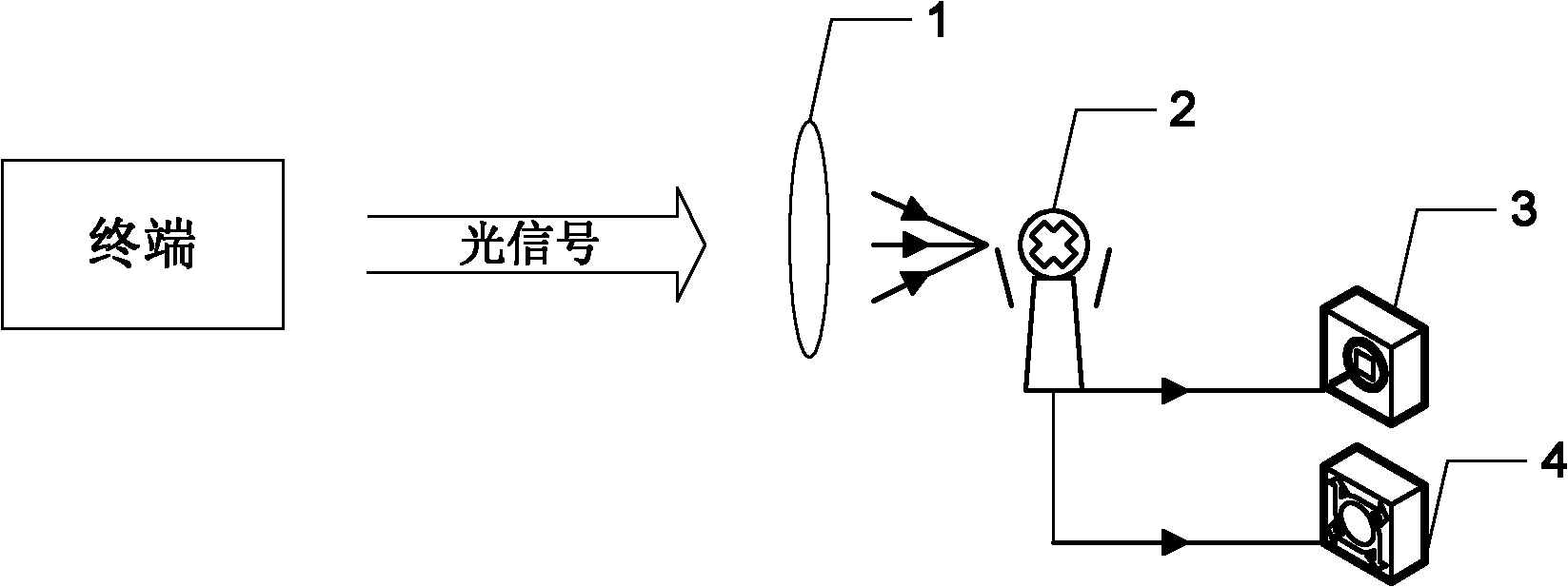
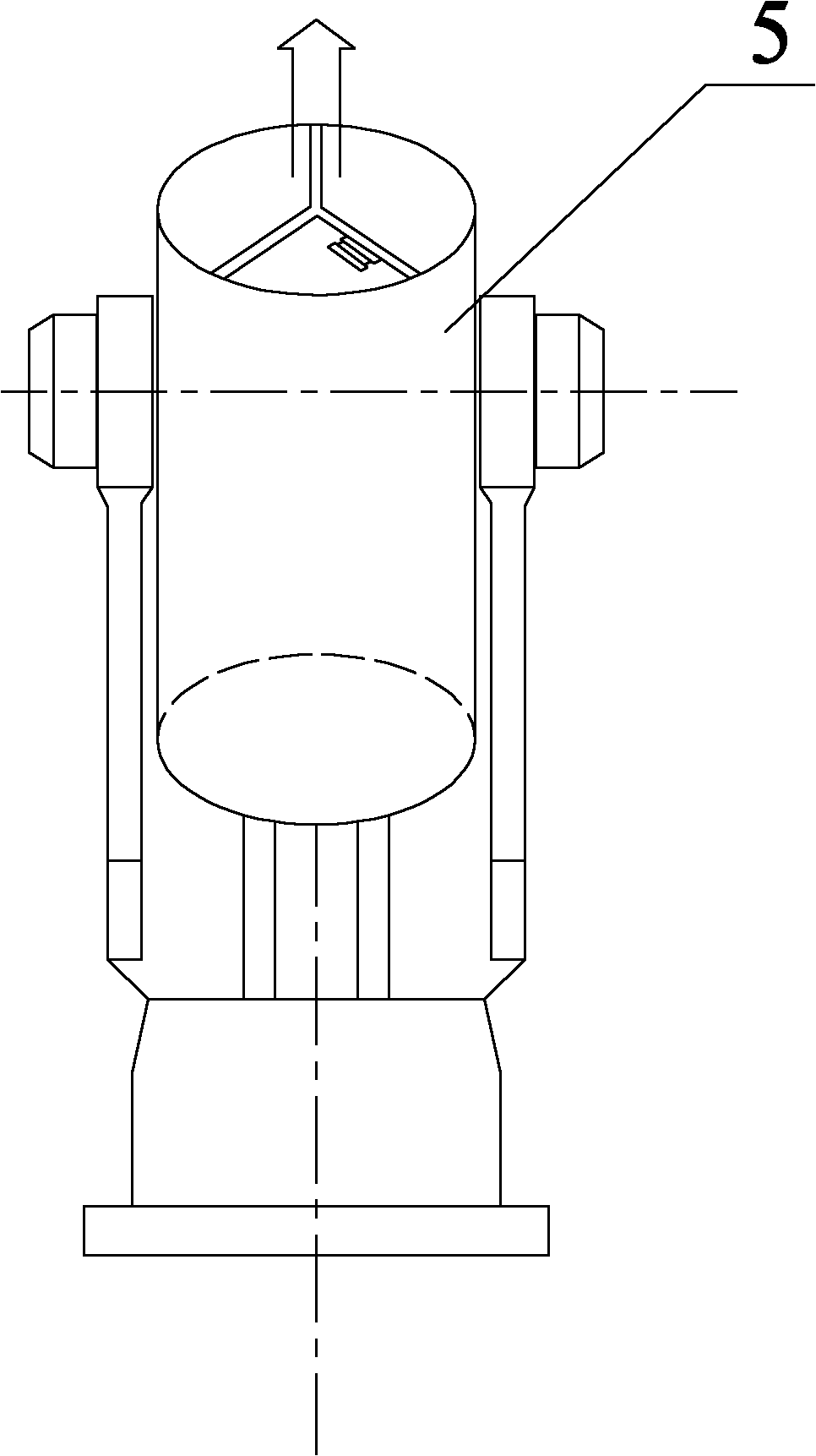
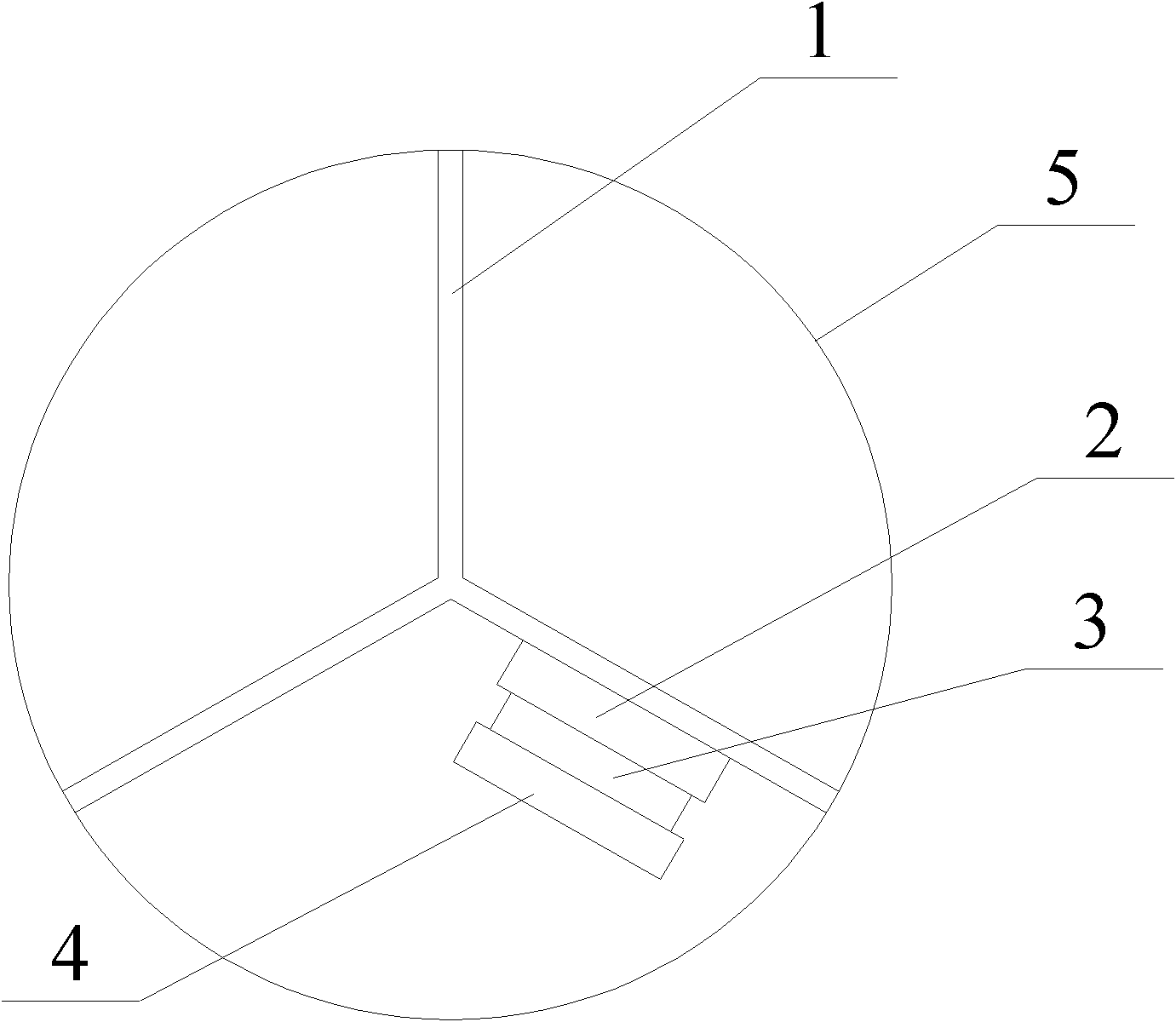
[0020] Specific implementation mode one: the following combination Figure 2 to Figure 5 Describe this embodiment, the satellite optical communication terminal described in this embodiment transmits optical signal performance follow-up test device, it comprises follow-up front-end test part and signal reception processing part, follow-up front-end test part is arranged on the optical signal of satellite optical communication terminal Inside the light output port of the antenna, the follower front-end test part includes a bracket 1, a miniature manual rotary table 2, a miniature angular displacement table 3 and a fiber collimator 4. The bracket 1 is fixed at the light output port of the optical antenna, and the base of the miniature manual rotary table 2 is fixed. On the support 1, a miniature angular displacement stage 3 is fixedly arranged on the turntable surface of the miniature manual rotary table 2, and a fiber collimator 4 is fixedly arranged on the turntable surface of t...
specific Embodiment approach 2
[0031] Specific implementation mode two: the following combination Figure 2 to Figure 5 This embodiment is described. This embodiment is based on the test method of the satellite optical communication terminal transmitting optical signal performance follow-up test device described in Embodiment 1, which includes the following steps:
[0032] Step 1. Set the follow-up front-end test part inside the optical antenna output port of the satellite optical communication terminal;
[0033] Step 2. Adjust the angle of the fiber collimator 4 with the micro angular displacement stage 3, and adjust the relative position of the fiber collimator 4 on the support 1 with the micro manual rotary table 2, so that the light entrance of the fiber collimator 4 is aligned The propagation direction of the optical signal in the optical antenna, and avoid aiming at the no-light area of the optical antenna;
[0034] Step 3. At the same time, observe the output curve of the power meter 6 and the outpu...
PUM
 Abstract
Description
Claims
Application Information
 - R&D
- Intellectual Property
- Life Sciences
- Materials
- Tech Scout
- Unparalleled Data Quality
- Higher Quality Content
- 60% Fewer Hallucinations
Browse by: Latest US Patents, China's latest patents, Technical Efficacy Thesaurus, Application Domain, Technology Topic, Popular Technical Reports.
© 2025 PatSnap. All rights reserved.Legal|Privacy policy|Modern Slavery Act Transparency Statement|Sitemap|About US| Contact US: help@patsnap.com


