Separating device for separating particles able to be magnetized and particles not able to be magnetized transported in a suspension flowing through a separating channel

A separation channel and separation device technology, applied in magnetic separation, solid separation, high-gradient magnetic separation, etc., can solve problems such as inability to ensure separation, small magnetic field gradient/magnetic field strength, etc., and achieve the effect of improving separation characteristics

Active Publication Date: 2011-08-17
SIEMENS AG
View PDF4 Cites 0 Cited by
  • Summary
  • Abstract
  • Description
  • Claims
  • Application Information

AI Technical Summary

Problems solved by technology

[0004] The disadvantage, however, is that the magnetic field gradients/field strengths generated by

Method used


Image

  • Separating device for separating particles able to be magnetized and particles not able to be magnetized transported in a suspension flowing through a separating channel
  • Separating device for separating particles able to be magnetized and particles not able to be magnetized transported in a suspension flowing through a separating channel
  • Separating device for separating particles able to be magnetized and particles not able to be magnetized transported in a suspension flowing through a separating channel

Examples


Embodiment Construction

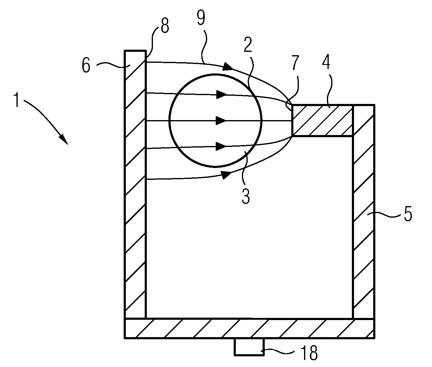
[0023] figure 1 A schematic sketch of the essential components of the separating device 1 according to the invention is shown. The separation device comprises a duct 2 extending perpendicular to the plane of the drawing, which defines a separation channel 3 equipped with a suspension containing magnetizable and non-magnetizable particles. The task of the separating device 1 is to allow the separation of magnetizable and non-magnetizable particles. For this purpose, a permanent magnet 4 is provided which is arranged on one side of the separation channel 3 , by means of which a deflection magnetic field is to be generated which deflects the magnetizable particles towards the side of the permanent magnet 4 . It should be noted here that instead of one permanent magnet 4 a plurality of permanent magnets connected in series can also be provided.

[0024] In order to optimize the magnetic field behavior inside the separating channel 3 and to improve the magnetic field strength, th...


PUM


Abstract

The invention relates to a separating device (1, 10, 14, 16, 17) for separating particles able to be magnetized and particles not able to be magnetized transported in a suspension flowing through a separating channel (3), having at least one permanent magnet (4, 4a, 4b, 4c, 4d) arranged on at least one side of the separating channel (3) for producing a magnetic field gradient which deflects particles able to be magnetized to said side, wherein a yoke (5) is provided for closing the magnetic circuit from the permanent magnet (4, 4a, 4b, 4c, 4d) to the side of the separating channel (3) opposite the permanent magnet (4, 4a, 4b, 4c, 4d) and/or between two permanent magnets (4, 4a, 4b, 4c, 4d).

Description

technical field [0001] The invention relates to a separation device for separating magnetizable and non-magnetizable particles transported in a suspension flowing through a separation channel, the separation device having at least one permanent magnet arranged on at least one side of the separation channel for A magnetic field gradient is generated that deflects the magnetizable particles towards this side. Background technique [0002] Especially in the field of mining or in the field of waste separation, it is often necessary to separate particles with different magnetic properties from one another, in particular to separate magnetizable particles from non-magnetizable particles. For this purpose, it is proposed to arrange one or more permanent magnets in the vicinity of, for example, the separating channel defined by the pipe, so that a magnetic field gradient is generated inside the pipe. The suspension, which contains magnetizable and non-magnetizable particles, is the...

Claims


Application Information

Patent Timeline
IPC IPC(8): B03C1/28B03C1/033
CPCB03C1/0335B03C1/002B03C2201/18B03C1/288B03C1/0332
Inventor B·特劳特曼K·本德J·奥斯瓦尔德W·施密特
Owner SIEMENS AG
Why Eureka
Try Eureka