Battery and battery pack

A technology of battery packs and batteries, which is applied in the manufacture of battery pack components, secondary batteries, and secondary batteries, and can solve the problem that battery heat cannot be effectively discharged and achieve the effect of improving safety

Inactive Publication Date: 2011-08-17
PANASONIC CORP
View PDF7 Cites 5 Cited by
  • Summary
  • Abstract
  • Description
  • Claims
  • Application Information

AI Technical Summary

Problems solved by technology

Therefore, there is a problem that the heat emitted by the battery as a whole cannot be effectively discharged to the outside of the battery.

Method used


Image

  • Battery and battery pack
  • Battery and battery pack
  • Battery and battery pack

Examples


no. 1 Embodiment approach

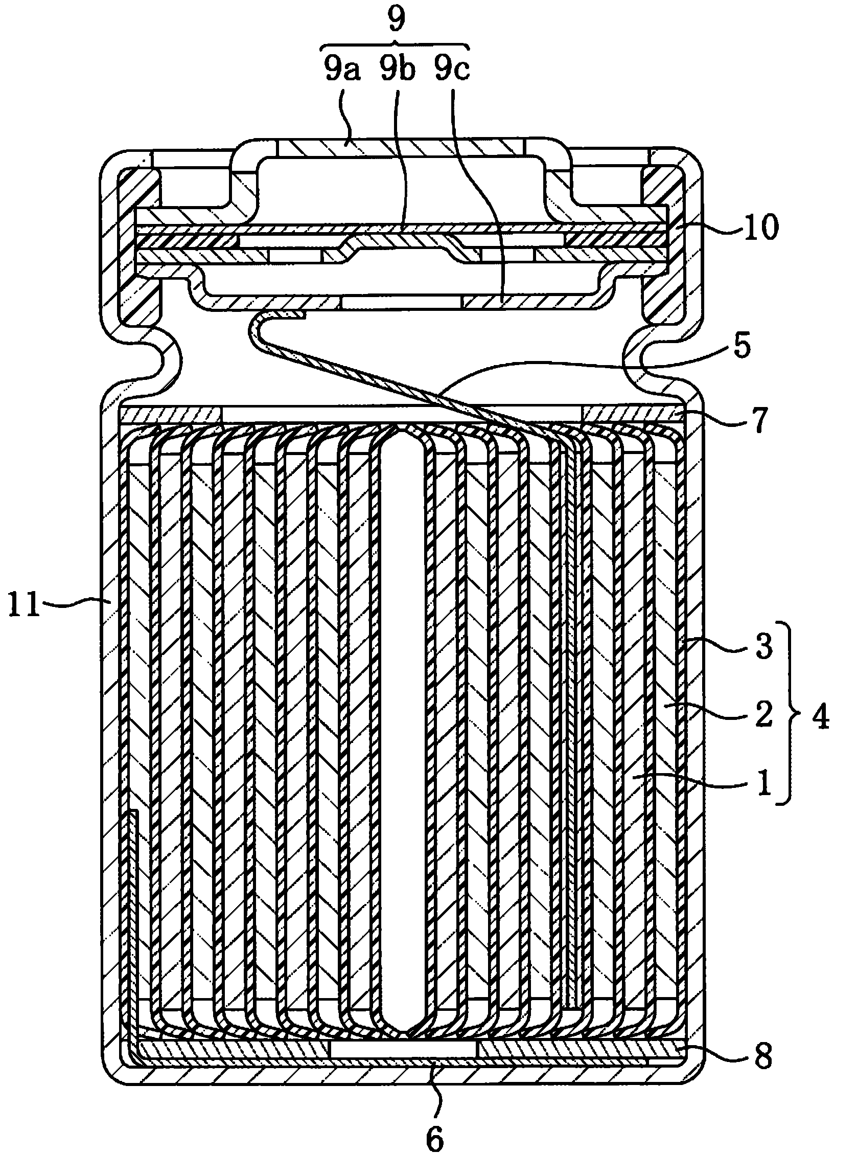
[0082] Hereinafter, for the battery of the first embodiment of the present invention, refer to figure 1 In the description, a cylindrical lithium-ion secondary battery is taken as an example of the battery. figure 1 It is a cross-sectional view showing the structure of the battery according to the first embodiment of the present invention.

[0083] Such as figure 1 As shown, the electrode group 4 is housed in a bottomed cylindrical battery case 11 together with the non-aqueous electrolytic solution. An annular upper insulating plate 7 is disposed on the upper portion of the electrode group 4 , and an annular lower insulating plate 8 is disposed on the lower portion of the electrode group 4 . The opening of the battery case 11 is caulked to the peripheral edge of the sealing plate 9 via the gasket 10 , whereby the opening of the battery case 11 is sealed.

[0084] The electrode group 4 is formed by winding the positive electrode plate 1 and the negative electrode plate 2 bet...

no. 2 Embodiment approach

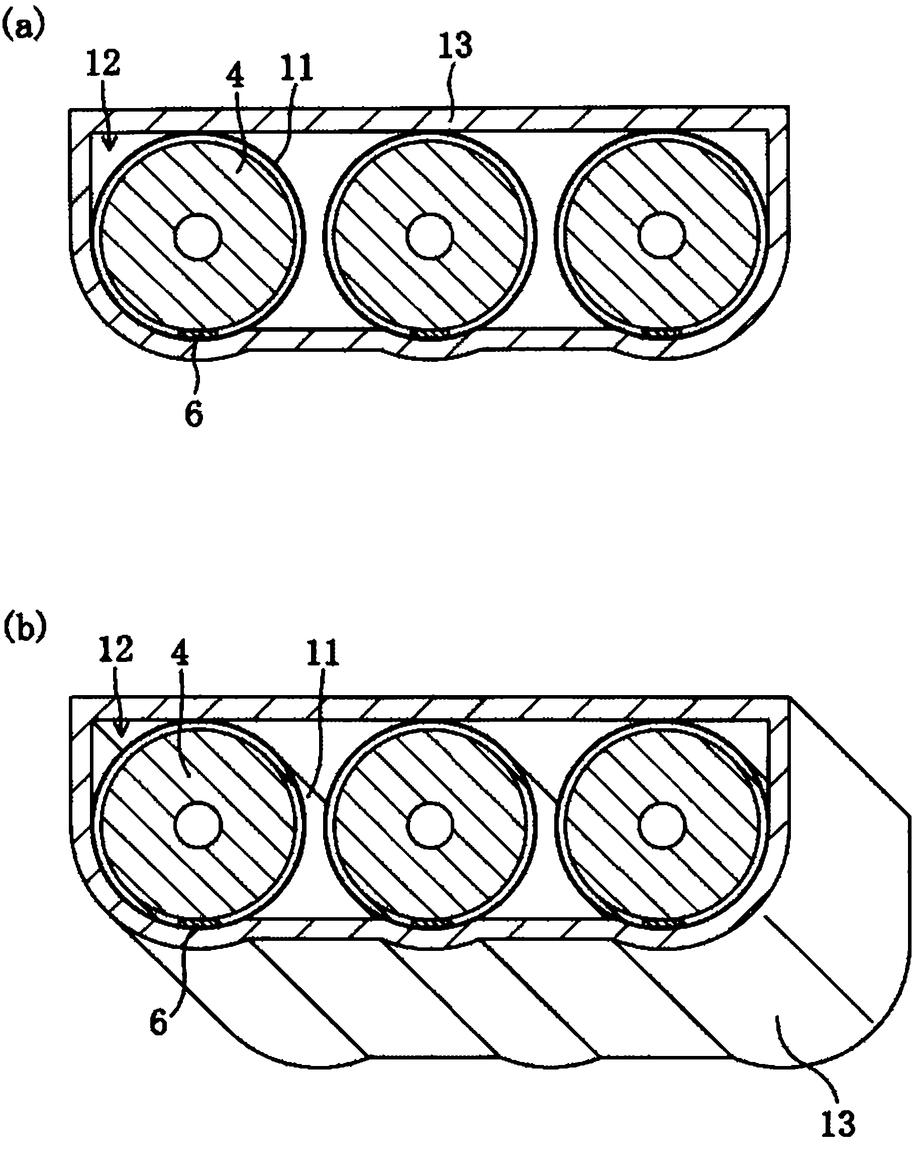
[0097] Hereinafter, for the battery pack according to the second embodiment of the present invention, refer to figure 2 (a) to (b) will be described. figure 2 (a) to (b) are diagrams showing the configuration of the battery pack according to the second embodiment of the present invention, specifically, figure 2 (a) is a sectional view, figure 2 (b) is a sectional perspective view.

[0098] The battery pack of this embodiment is a battery pack in which the battery 12 of the first embodiment is enclosed in a battery pack case 13 .

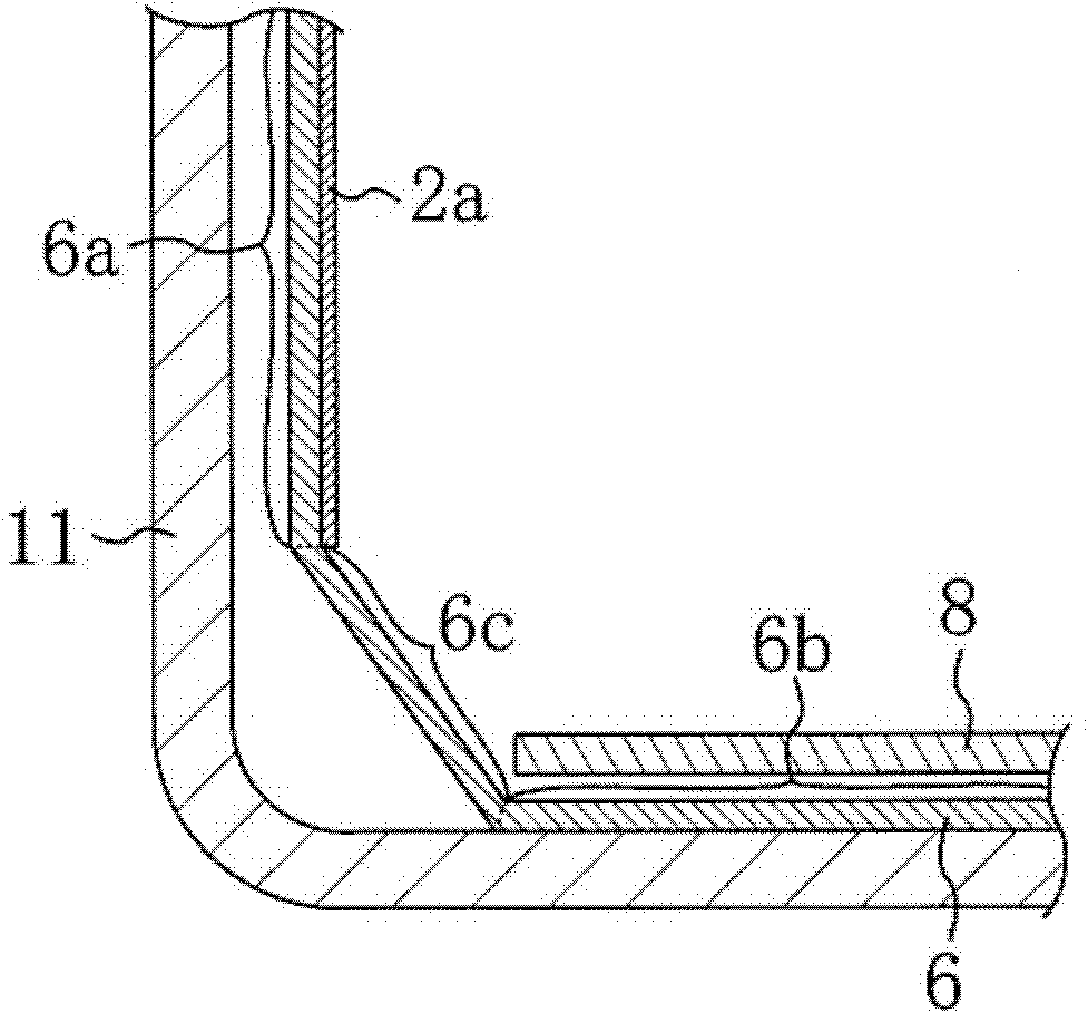
[0099] Such as figure 2 As shown in (a) to (b), the battery 12 is arranged in the battery pack case 13 based on the position of the negative electrode internal lead 6 judged by the display means. Specifically, the part of the outer surface of the battery case 11 corresponding to the inner lead 6 for the negative electrode, in other words, one end of the inner lead 6 for the negative electrode of the battery case 11 (refer to image 3 : 6a) ...

Embodiment 1

[0199] Hereinafter, for the manufacturing method of the battery of Example 1, refer to figure 1 Be explained.

[0200] (1) Production of positive plate

[0201] In 100 parts by weight of lithium cobaltate (LiCoO) with an average particle size of 10 μm as the positive electrode active material 2 ), 8 parts by weight of PVdF as a binder, and 3 parts by weight of acetylene black as a conductive agent, add an appropriate amount of N-methyl-2-pyrrolidone (NMP) and mix to obtain a positive electrode mixture paste.

[0202] Then, on both faces of the positive electrode current collector made of a strip-shaped aluminum foil with a length of 600 mm, a width of 54 mm, and a thickness of 20 μm, remove the central part of the positive electrode current collector (that is, the positive electrode is connected with the inner lead). The positive electrode mixture paste was applied to the portion other than the exposed portion of the positive electrode current collector. Thereafter, the pos...


PUM

PropertyMeasurementUnit
thicknessaaaaaaaaaa
widthaaaaaaaaaa
widthaaaaaaaaaa

Abstract

Disclosed is a battery pack provided with a plurality of batteries (12) and a pack case (13) in which the plurality of batteries (12) are sealed. A set of electrodes, comprising a positive plate and a negative plate wound or layered around a porous insulating layer, is contained along with an electrolyte solution in a battery case (11), and the opening of the battery case (11) is sealed by a sealing plate. A first internal lead (6), which is electrically connected to either the positive plate or the negative plate, is connected to the inside bottom part of the battery case (11). A second internal lead, which is electrically connected to the other electrode plate, is connected to the sealing plate. The first internal lead (6) is disposed up against the inner surface of the battery case (11). The plurality of batteries (12) are disposed in the pack case (13) such that an area on the outer surface of each battery case (11) corresponding to the first internal lead (6) of that battery faces an inner surface of the pack case (13).

Description

technical field [0001] The present invention relates to batteries and batteries (also referred to as battery packs), and more particularly to batteries and batteries having internal leads electrically connecting the battery case and the electrode pack. Background technique [0002] As a conventional battery, an electrode group composed of a positive electrode plate, a negative electrode plate, and a separator is housed in a battery case together with an electrolytic solution, and the opening of the battery case is sealed with a sealing plate. The battery has an inner lead for the negative electrode electrically connecting the negative electrode plate and the inner bottom of the battery case, and an inner lead for the positive electrode electrically connecting the positive electrode plate and the sealing plate. [0003] In addition, as a conventional battery pack, a battery pack obtained by enclosing a plurality of batteries in a battery pack case is used. [0004] When an e...

Claims


Application Information

Patent Timeline
Patent Type & Authority Applications(China)
IPC IPC(8): H01M2/02H01M2/04H01M2/10H01M2/26H01M10/04H01M10/50H01M50/528
CPCY02E60/12H01M2/105H01M10/5051H01M2/22H01M2/023H01M2/1241H01M2/342H01M10/503H01M2/204H01M10/6553H01M10/643Y02E60/10H01M50/56H01M50/213H01M50/3425H01M50/528H01M50/597Y02P70/50H01M50/531
Inventor 清水启介横山智彦藤川万乡
Owner PANASONIC CORP
Why Eureka
Try Eureka