Precipitation construction method employing pipe embedded in deep foundation pits

A construction method and technology for deep foundation pits, applied in infrastructure engineering, construction and other directions, can solve problems such as hidden dangers of underground engineering waterproofing, affecting the progress of the construction period, wasting groundwater resources, etc., so as to shorten the construction period, improve the waterproof effect, and reduce engineering costs The effect of cost

Active Publication Date: 2012-09-19
山东新城建工股份有限公司
View PDF0 Cites 0 Cited by
  • Summary
  • Abstract
  • Description
  • Claims
  • Application Information

AI Technical Summary

Problems solved by technology

[0003] The above several existing construction methods have the following disadvantages: 1. Drilling deep wells around the foundation pit for dewatering will waste a lot of groundwater resources and easily endanger the original buildings on the edge; The waterproof construction and the plugging of the dewatering well are another technical problem. The waterproof layer below the base plate is not easy to construct. After the dewatering well is blocked, construction joints will be formed on the base plate. Leakage causes great hidden dangers to the waterproofing of underground works; ③The precipitation effect in the middle of the foundation pit is poor. In order to achieve the precipitation effect, the depth of the precipitation well must be increased, which will inevitably increase the precipitation cost and increase the project cost. The extension of time will affect the progress of the construction period

Method used


Image

  • Precipitation construction method employing pipe embedded in deep foundation pits
  • Precipitation construction method employing pipe embedded in deep foundation pits

Examples


Embodiment Construction

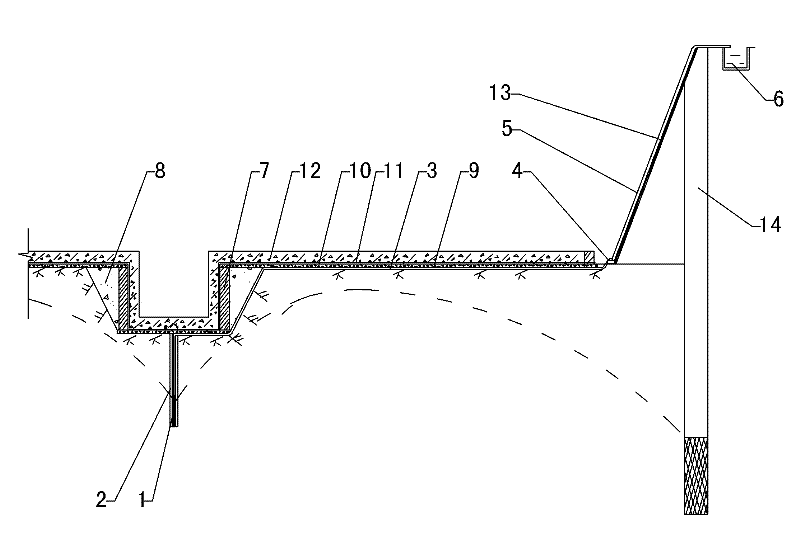
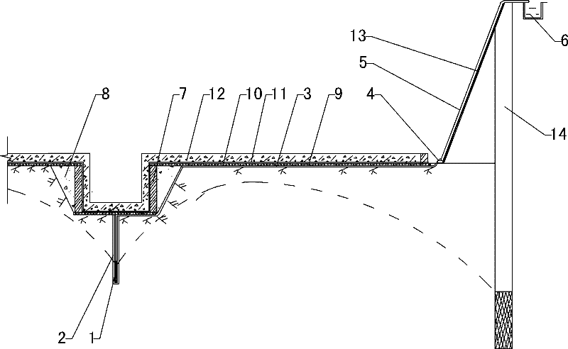
[0020] Refer to attached figure 1 :

[0021] The deep foundation pit buried pipe dewatering construction method comprises the following steps,

[0022] a. According to the engineering drawings and geological conditions, excavate the foundation pit. When the earthwork is excavated to 1m above the design bottom elevation of the engineering foundation pit, the position of the elevator pit or sump pit to be dug is accurately measured, and the excavator is used in the middle of the foundation pit. Dig a pit reaching 100mm below the level of the bottom of the foundation pit as an elevator pit or sump;

[0023] b. Use an excavator to vertically press a section of steel pipe with a diameter of 100mm into the middle of the elevator pit or sump, then take out the steel pipe to form a vertical wellbore with a diameter of 100mm, and then vertically install the PVC filter pipe 1 Installed in the wellbore, the diameter of the PVC filter pipe 1 is 40mm;

[0024] c. Fill the gap between th...


PUM


Abstract

The invention relates to a precipitation construction method employing pipe embedding in deep foundation pits and belongs to the field of building construction technology. The construction method comprises the steps of: a, when earth is dug to a depth 1 meter above a designed bottom elevation of an engineering foundation pit, accurately measuring a position of an elevator pit or a catch pit in the foundation pit, and digging a pit reaching 100 millimeters below the pit bottom elevation in the middle of the foundation pit with an excavator; b, pressing a portion of a steel pipe into the middle of the elevator pit or the catch pit with the excavator, taking out the steel pipe for forming a borehole, and installing a PVC filter pipe (1) in the borehole vertically; c, fixing one end of a PPR embedded pipe (3) and the upper end of the PVC filter pipe (1) in a pluggable manner and drawing the other end of the PPR embedded pipe (3) to the outside of the foundation; d, installing a self-priming pump (4) on the other end of the PPR embedded pipe (3) and connecting a PPR pipe pump lift (5) to the self-priming pump (4); and e, when the precipitation elevation is achieved, digging the earth to the designed elevation of the pit bottom and pouring a concrete cushion (9) at the bottom of the elevator pit or the catch pit. The construction method effectively reduces a precipitation depth of the periphery of the foundation pits, saves groundwater resources, avoids dangers for surrounding buildings and achieves excellent waterproofness.

Description

technical field [0001] The invention relates to a deep foundation pit buried pipe dewatering construction method, which belongs to the technical field of building construction, and specifically relates to local dewatering at elevator pits and sump pits with high groundwater level and large underground engineering area, which are lower than the bottom plate of the foundation pit. Background technique [0002] With the development of construction technology, building foundation pit projects continue to extend underground, and the dewatering of building foundation pits is a big problem, especially for projects with large width and depth of foundation pits and large underground water content. The existing dewatering technology is to drill deep wells around the foundation pit for dewatering or to drill wells around the foundation pit. The elevator pit and sump in the foundation pit are partially drilled for dewatering. After the waterproof floor concrete is poured there, the dewat...

Claims


Application Information

Patent Timeline
Patent Type & Authority Patents(China)
IPC IPC(8): E02D19/20
Inventor 王玉伦崔佃和伊功善韩爱强朱立东荆茂农
Owner 山东新城建工股份有限公司
Why Eureka
Try Eureka