Projector and optical path control method thereof

A control method and projector technology, applied in the field of projection display, can solve the problems of high professional requirements of operators, complicated operation, difficult to popularize, etc., and achieve the effect of convenient popularization, simple operation, and easy operation.

Active Publication Date: 2011-08-24
威海慧视生物科技有限公司
View PDF9 Cites 9 Cited by
  • Summary
  • Abstract
  • Description
  • Claims
  • Application Information

AI Technical Summary

Problems solved by technology

The playing method of the above-mentioned 3D movie is very expensive and the operation is very complicated. First, the position of the screen must be fixed in advance, and then the focus of the two projectors and the tilt angle of the projection lens need to be adjusted to make the image projected on the screen High-precision coincidence requires high professionalism of the operator, and it is difficult to popularize. Currently, it is only used in theaters.

Method used


Image

  • Projector and optical path control method thereof
  • Projector and optical path control method thereof
  • Projector and optical path control method thereof

Examples


Embodiment Construction

[0015] The present invention will be described in further detail below in combination with specific embodiments and with reference to the accompanying drawings.

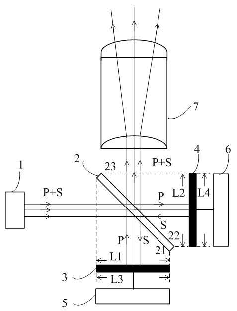
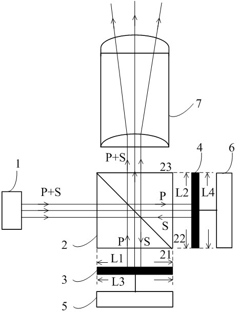
[0016] Such as figure 1 As shown, it is the internal optical path diagram of the projector according to the specific embodiment. The projector includes a light source 1 , a polarization splitting unit 2 , a first micro display chip 3 , a second micro display chip 4 , a first six-axis adjustment device 5 , a second six-axis adjustment device 6 and a projection lens 7 .

[0017] Wherein, the light source 1 is an LED emitting an illumination beam. In addition to LEDs, other non-polarized light sources such as halogen lamps can also be used as the light source, and linearly polarized light sources including P-polarized light and S-polarized light can also be used.

[0018] The polarization beam splitter 2 is a grating polarization beam splitter, which receives light beams, reflects S-polarized light in the received lig...


PUM


Abstract

The invention discloses a projector. The projector comprises a light source, a polarizing beam splitting unit, a first micro-display chip, a second micro-display chip, a first six-axis adjustment device, a second six-axis adjustment device and a projection lens, wherein the light source is used for emitting an illumination beam; the illumination beam is split by the polarizing beam splitting unitto obtain an S-polarized beam and a P-polarized beam; and the S-polarized beam and the P-polarized beam are respectively modulated and combined to one beam through the space arrangement of the polarizing beam splitting unit, the first micro-display chip, the second micro-display chip and the projection lens. Therefore, the beam emitted by the projector contains the S-polarized beam and the P-polarized beam, thereby achieving 3D display by projecting the beam on a metal screen. The projector has low cost, miniaturized design and convenience in operation, and has no obvious difference with the common 2D projector in the playing, focusing and other operations. Therefore, the projector is convenient in operation when being used for playing 3D movies so as to facilitate the popularization of 3D movies, and the common people can watch 3D images at home.

Description

technical field [0001] The invention relates to the field of projection display, in particular to a projector and a method for controlling its optical path. Background technique [0002] The existing 3D movie playback is a dual-lens mode, which requires two identical ordinary projectors, respectively adding mutually orthogonal linear polarization lenses in front of the projection lenses of the two projectors, and through the polarization effect of the linear polarization lenses on the light beam, The two linearly polarized lenses emit S-polarized light and P-polarized light respectively, and project the S-polarized light and P-polarized light onto a screen that does not change the polarization state of the incident light, such as a metal screen or a frosted screen. Afterwards, the viewer wears 3D glasses, and the left and right lenses of the 3D glasses use polarized lenses with different polarization directions respectively, so that the left and right eyes of the viewer can ...

Claims


Application Information

Patent Timeline
Patent Type & Authority Applications(China)
IPC IPC(8): G03B21/00G03B21/20G03B21/14G02B27/28G02B27/10
Inventor 程雪岷廖汉忠林家用
Owner 威海慧视生物科技有限公司
Why Eureka
Try Eureka