Drinking water supply device
A technology for supplying devices and beverages, applied in the field of hygienic conditions in passages, to achieve the effect of preventing bacteria from mixing, improving hygienic conditions, and maintaining hygienic conditions
- Summary
- Abstract
- Description
- Claims
- Application Information
AI Technical Summary
Problems solved by technology
Method used
Image
Examples
no. 1 approach
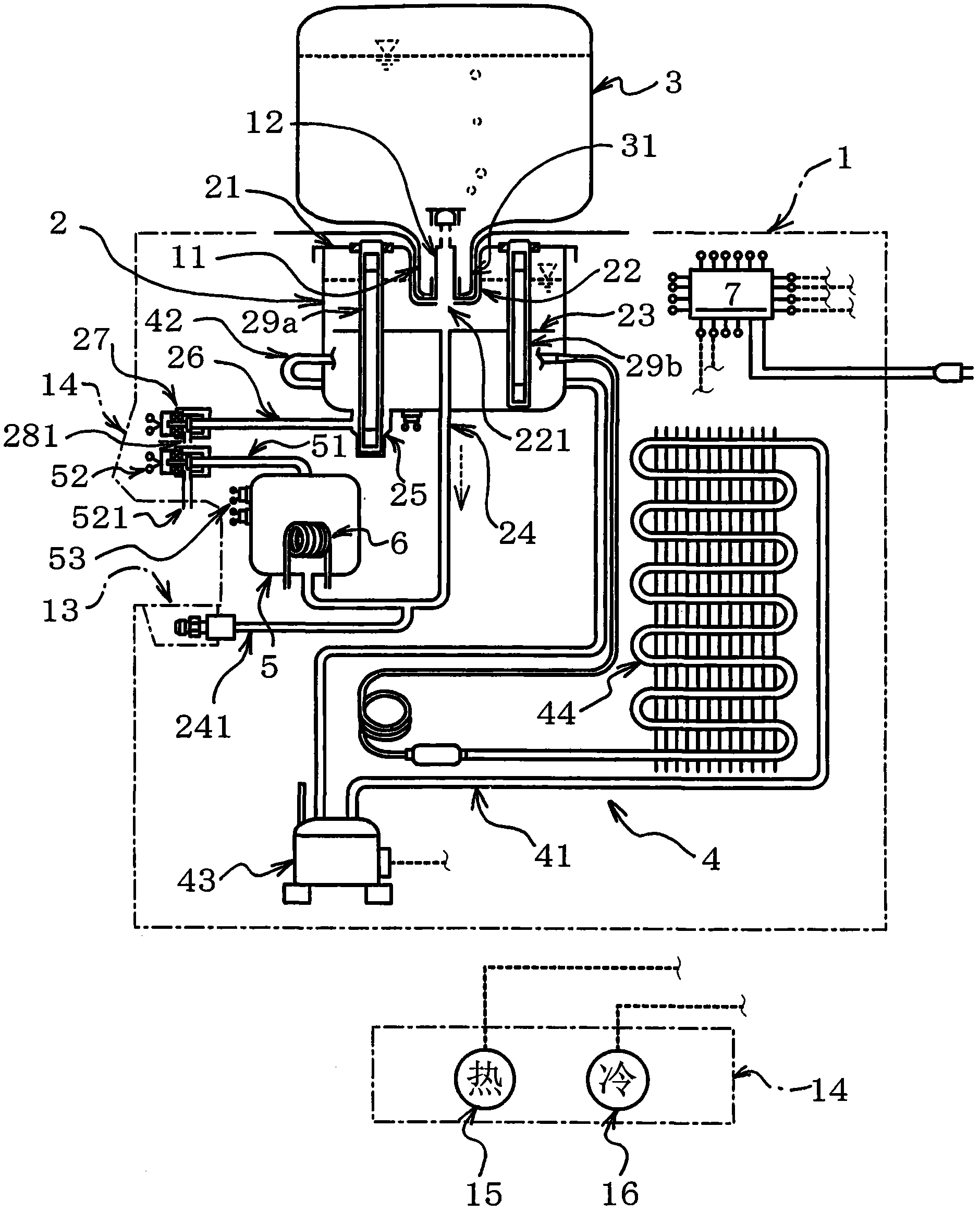
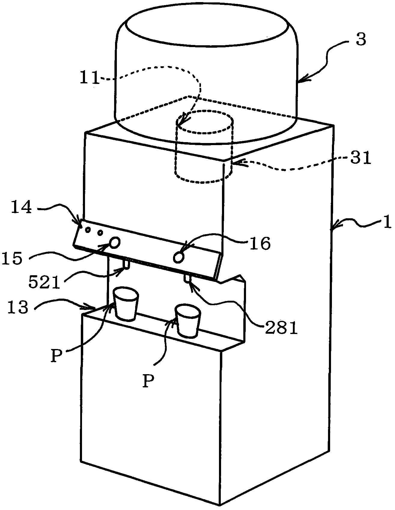
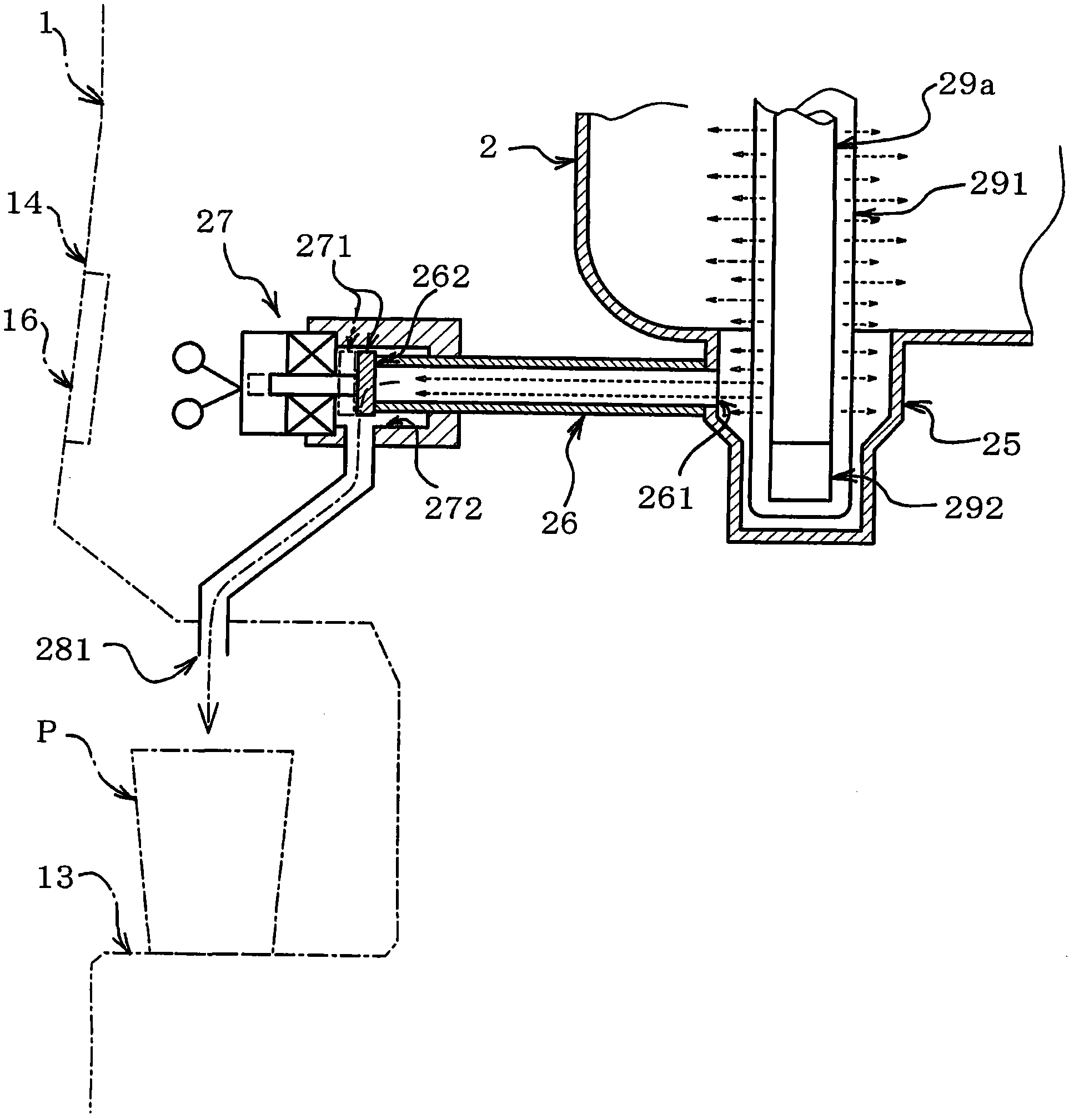
[0035] In the drinking water supply device having the above overall structure, such as Figure 4 As shown, a curved portion 282 is formed in the vicinity of the water intake 281 in the water intake outlet pipe 28 constituting a passage from the cold water intake valve 27 as an on-off valve to the water intake 281 . The curved portion 282 is formed so as to be curved with a corner edge 283 . That is, the curved portion 282 is not curved smoothly, but is formed such that the inclination or gradient of the inner surface through which drinking water flows changes sharply with the corner edge 283 as the boundary. Furthermore, the passage inner wall surface 284 formed on the upstream side of the corner edge 283 across the corner edge 283 becomes an upward slope toward the water intake valve 27 . The water intake outlet pipe 28 constitutes a water intake outlet passage formed of pipes.
[0036] Explain in more detail. Such as Figure 4 As shown, the water intake outlet pipe 28 co...
no. 2 approach
[0043] Image 6 The water intake outlet pipe 28a in the drinking water supply device of the second embodiment is shown. This second embodiment differs from the first embodiment only in that the hole 289 for sucking air is formed on the water intake outlet pipe 28a, and is completely the same as the first embodiment in other respects, and has the same structure and structure as the first embodiment. Effect. Therefore, in the following description, differences will be mainly described, and the same reference numerals will be assigned to the same configurations, and repeated detailed descriptions will be omitted.
[0044] In the water intake pipe 28a of the second embodiment, one or two or more holes for sucking air are penetratingly formed on the channel inner wall surface 288 at a position near the downstream side of the corner edge 283 at the innermost position of the bent portion 282. 289. The hole size of the hole 289 is set to such a small size that water hardly passes t...
Embodiment approach
[0051] In addition, the present invention is not limited to the above-described embodiments, but includes other various embodiments. That is, as an object to which the present invention is applied, even figure 1 The present invention can also be applied to structures other than those illustrated. For example, as an ultraviolet lamp for sterilization, the structure illustrated is one used as an ultraviolet lamp 29a linked with water intake, and one used as an ultraviolet lamp 29b for regular lighting, but it is not limited to this, and many can also be used as Most of the ultraviolet lamps linked to water intake are only used as ultraviolet lamps for periodic lighting. In addition, although the structure having the hot water tank 5 in addition to the cold water tank 2 has been described as an example, the hot water tank 5 can be omitted to constitute a drinking water supply device that can only take cold water from the cold water tank 2 . Furthermore, as long as it is a drin...
PUM
 Abstract
Description
Claims
Application Information
 - R&D
- Intellectual Property
- Life Sciences
- Materials
- Tech Scout
- Unparalleled Data Quality
- Higher Quality Content
- 60% Fewer Hallucinations
Browse by: Latest US Patents, China's latest patents, Technical Efficacy Thesaurus, Application Domain, Technology Topic, Popular Technical Reports.
© 2025 PatSnap. All rights reserved.Legal|Privacy policy|Modern Slavery Act Transparency Statement|Sitemap|About US| Contact US: help@patsnap.com


