Dye spin-coating apparatus for DVDR optical discs

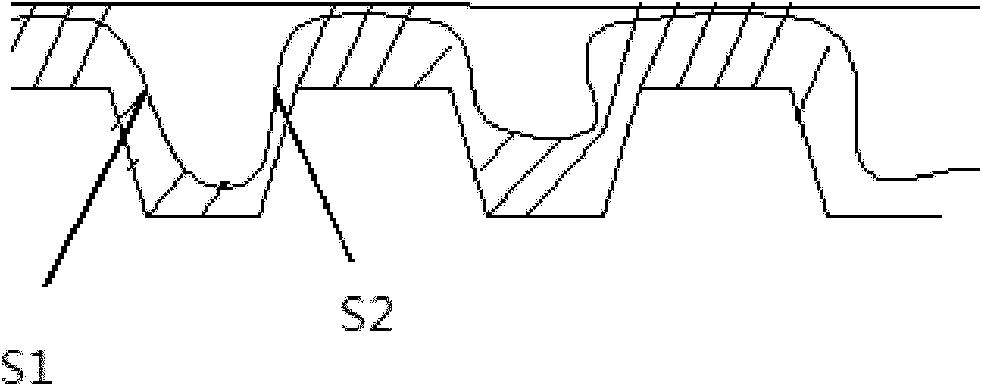
A technology for dyes and optical discs, which is applied to devices and coatings that apply liquid to the surface. It can solve problems such as data deviation, affecting spot focusing and tracking, and tracking errors, shortening time, improving production efficiency, and reducing grooves. The effect of increasing the area

Inactive Publication Date: 2013-10-02
上海拓引数码技术有限公司
View PDF0 Cites 0 Cited by
  • Summary
  • Abstract
  • Description
  • Claims
  • Application Information

AI Technical Summary

Problems solved by technology

However, after careful analysis and comparison of the groove morphology of some master disks, it is found that it is difficult to fully infiltrate the grooves of the outer ring of the substrate in a relatively short period of time by using the dye spin coating device in the prior art to perform dye spin coating. Most of them rely on the dye to spread from the inner ring to the outer ring under the action of centrifugal force, so that the dye can be applied to the groove surface of the disc.
[0003] like figure 1 As shown, since the substrate groove is shallow and wide, the dye is diffused into the adjacent groove under the action of centrifugal force in the groove that is not infiltrated when the dye solution is applied, forming a deposition thickness of S1 on one side of the groove, The S2 deposition on the other side is thin, which will inevitably affect the focusing and tracking of the light spot in the groove, which in turn will cause tracking errors and data deviations

Method used


Image

  • Dye spin-coating apparatus for DVDR optical discs
  • Dye spin-coating apparatus for DVDR optical discs
  • Dye spin-coating apparatus for DVDR optical discs

Examples


Embodiment Construction

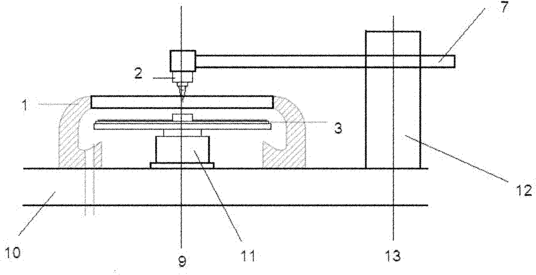
[0021] The preferred embodiments of the present invention will be given below in conjunction with the accompanying drawings, and will be described in detail, so that the functions and characteristics of the Blu-ray disc glue spin coating device of the present invention can be better understood.

[0022] like figure 2 As shown, according to a preferred embodiment of the present invention, the dye spin-coating device of a DVDR disc with a longitudinal central axis 9 includes: a substrate 10 arranged horizontally, a spin-coating bowl 1 fixed on the upper surface of the substrate 10; The inside of the spin-coating bowl 1 is provided with a guide post 11 along the central axis, and a spin-coating bowl tray 3 is horizontally provided with a predetermined height of the guide post 11 for placing discs to be processed; The outside of the spin-coating bowl 1 is horizontally provided with a dye mechanical arm 7, one end of the mechanical arm 7 is connected to the pillar 12 and can rotat...


PUM


Abstract

The invention provides a dye spin-coating apparatus for DVDR optical discs. The apparatus comprises a dye feeding system; a horizontally arranged base plate; a central shaft basically vertical to the base plate; a spin-coating bowl fixed on the upper surface of the base plate; a guide pillar disposed in the spin-coating bowl and along the central shaft; a spin-coating bowl pallet disposed horizontally at a height identical to the predetermined height of the guide pillar and used for placing the to-be-processed discs; and a dye-feeding mechanical arm horizontally disposed outside the spin-coating bowl. One end of the mechanical arm is connected with a pillar and rotates around the central shaft of the pillar, and the other end of the mechanical arm is provided with a needle controller as well as a main needle and an auxiliary needle, which are disposed below the needle head controller. The dye spin-coating apparatus in the invention, by employing double needle heads for the dye coating of the substrates, adequately solves the problem that dye solution is not evenly filled in outer rings of the substrates; and prolongs the time used for making the dye even during the dye spin-coating while reducing the overall spin-coating time, thereby improving the production efficiency and the spin-coating quality of the outer rings of DVDR products.

Description

technical field [0001] The invention relates to a production equipment of a DVDR disc, in particular to a dye spin coating device for a DVDR disc. Background technique [0002] The traditional DVD±R production generally uses dye spin coating under the robot, and the industry has gradually accepted and familiarized with it, and the spin coating process is also becoming mature. However, after careful analysis and comparison of the groove morphology of some master disks, it is found that it is difficult to fully infiltrate the grooves of the outer ring of the substrate in a relatively short period of time by using the dye spin coating device in the prior art to perform dye spin coating. In most cases, the dye can be applied to the groove surface of the disc only by the diffusion and promotion of the dye from the inner ring to the outer ring under the action of centrifugal force. [0003] like figure 1 As shown, since the substrate groove is shallow and wide, the dye is diffus...

Claims


Application Information

Patent Timeline
Patent Type & Authority Patents(China)
IPC IPC(8): B05C5/00B05C11/08
Inventor 郑飞璠宋国旗李恒夏芃马超
Owner 上海拓引数码技术有限公司
Why Eureka
Try Eureka