A Low-Voltage Driven Inverse Zoom Microlens

A micro-lens and low-voltage technology, applied in the field of micro-lens, can solve the problems of reducing device compactness, limited focal length adjustment range, electrode cracking, etc., and achieves high-efficiency manufacturing and uniformity, simple structure, and good integration.

Active Publication Date: 2019-07-02
XI AN JIAOTONG UNIV
View PDF4 Cites 0 Cited by
  • Summary
  • Abstract
  • Description
  • Claims
  • Application Information

AI Technical Summary

Problems solved by technology

For example, S.Y.Lee et al. proposed a zoom microlens array based on thermal effects, which has the advantages of low price and flexible structural design, but the manufacturing process is complicated, the response speed is slow, and the focusing range is small; the zoom microlens designed and manufactured by Jiang's research group The array uses the expansion and contraction characteristics of the hydrogel in different temperature environments to change the curvature of the water-oil interface to achieve the purpose of adjusting the focus. It can achieve a larger focus range, but the existence of the hydrogel channel greatly reduces the The compactness of the device reduces the duty cycle of the liquid microlens, and it is difficult to meet the high integration requirements; the liquid zoom lens based on the principle of electrowetting proposed by the S.Kuiper group has a flexible structure, but due to the limitation of high voltage, Usually the voltage is greater than 150V, the adjustment range of the focal length is limited, and it brings reliability and stability problems such as electrode rupture and breakdown failure.
Moreover, the zoom range of most of the microlenses currently studied is only limited to zooming in a limited range

Method used


Image

  • A Low-Voltage Driven Inverse Zoom Microlens
  • A Low-Voltage Driven Inverse Zoom Microlens
  • A Low-Voltage Driven Inverse Zoom Microlens

Examples


Embodiment Construction

[0024] The present invention will be described in detail below in conjunction with the accompanying drawings.

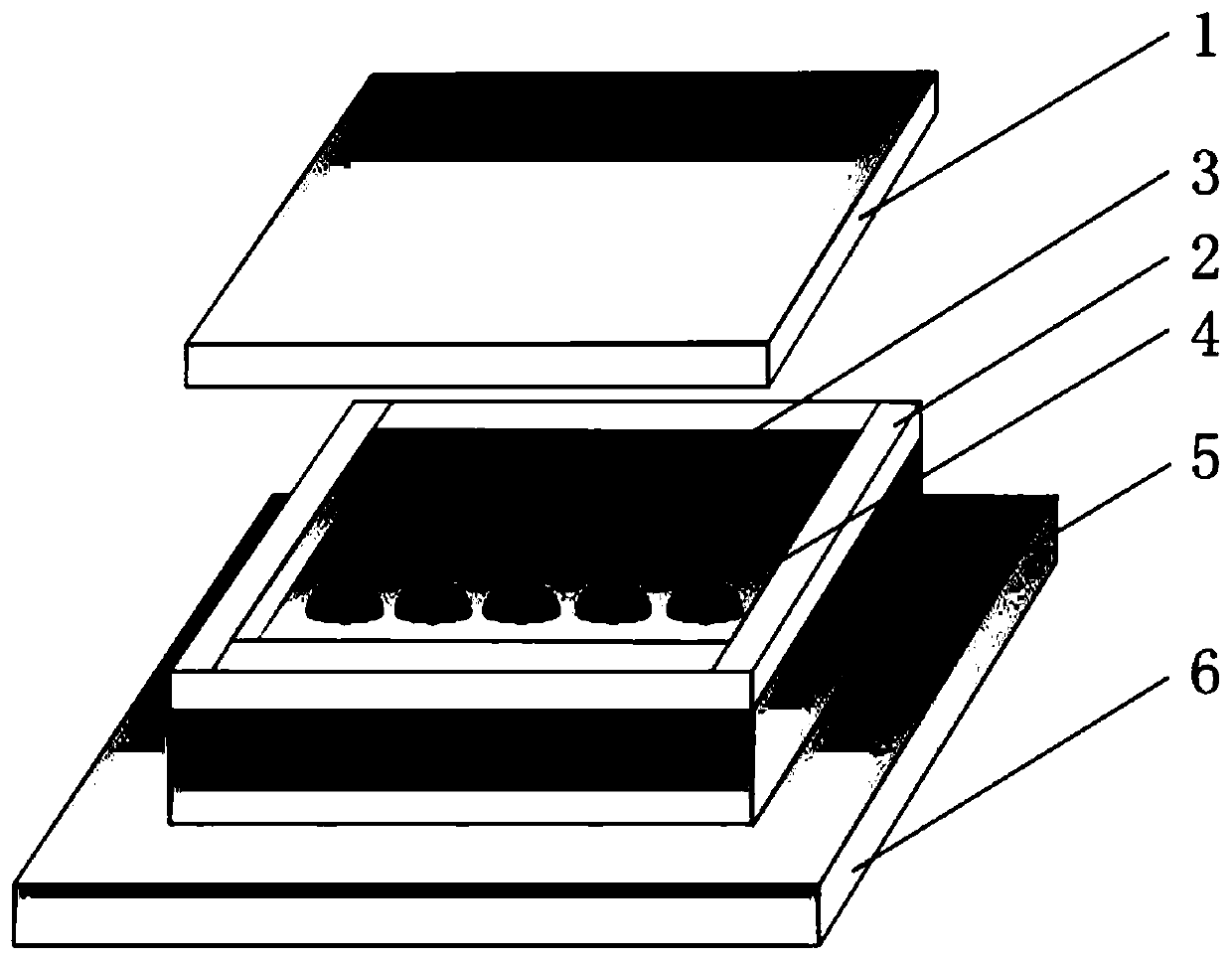
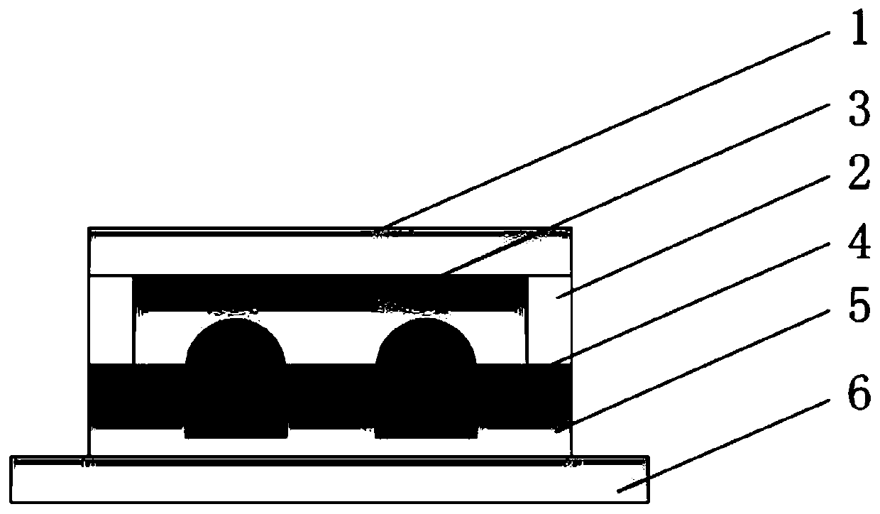
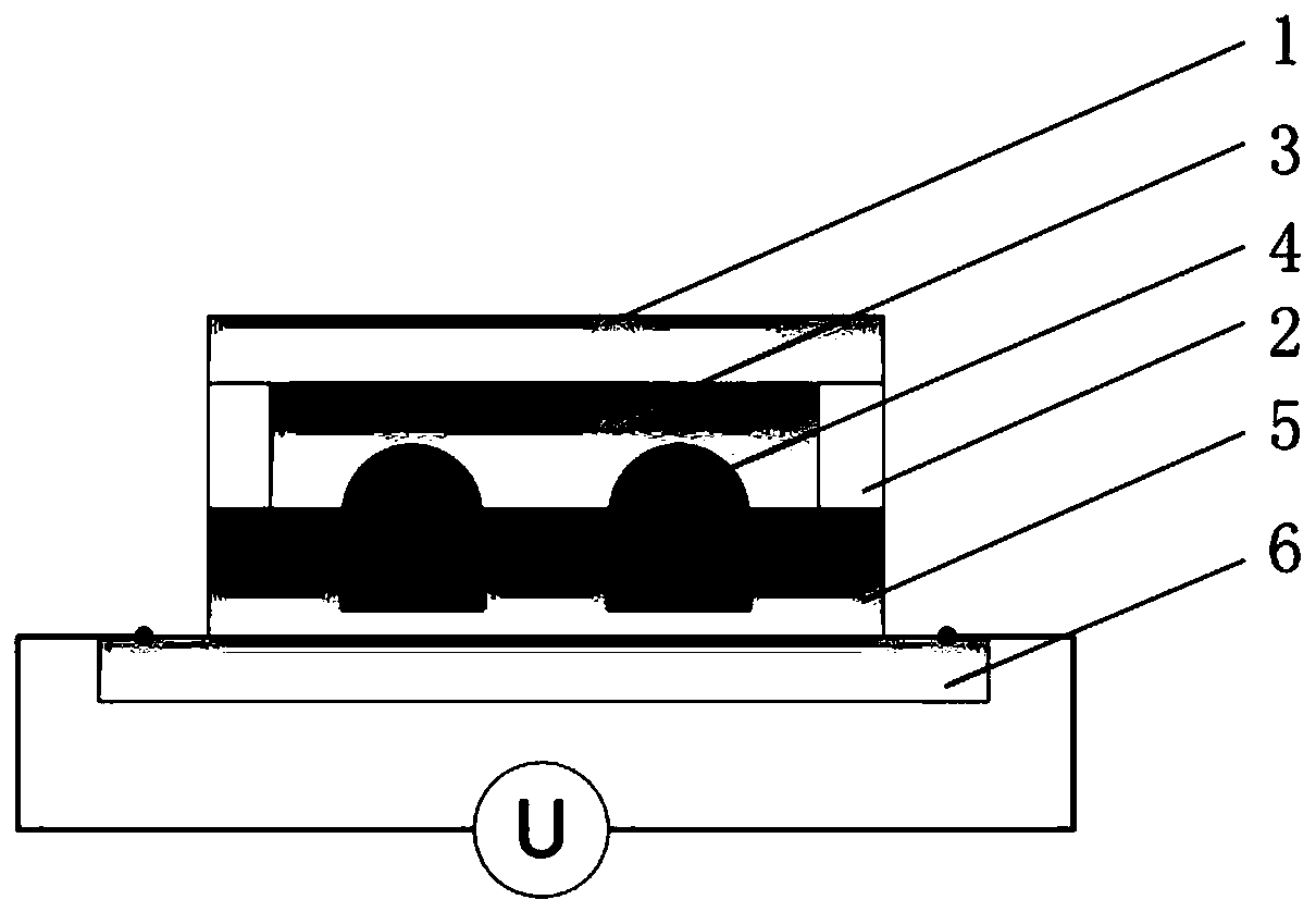
[0025] refer to Picture 1-1 and Figure 1-2 , a low-voltage-driven reverse zoom microlens, including a bottom layer 6, the bottom layer 6 is a transparent conductive layer, as an electrode; The porous structure 5 is used as the middle layer; the first transparent solid plate 2 is connected around the porous structure 5, and the first transparent liquid 3 is housed on the top of the porous structure 5 and the first transparent solid plate 2, the first transparent solid plate 2 and the transparent The upper part of the liquid 3 is encapsulated by the second transparent solid plate 1, and the first transparent solid plate 2, the first transparent liquid 3, and the second transparent solid plate 1 constitute the top layer, which is an encapsulation protection layer.

[0026] The porous structure 5 is a periodic transparent micropore array.

[0027] The material of the...


PUM


Abstract

The invention discloses a reverse zoom microlens driven by low voltage. The reverse zoom microlens driven by low voltage comprises a bottom layer which is a transparent conductive layer; a porous structure embedded with a microlens array is arranged on the bottom layer, and the porous structure embedded with the microlens array is used as a middle layer; a first transparent solid plate is connected around the porous structure, first transparent liquid is loaded on the upper part of the porous structure and inside the first transparent solid plate; upper parts of the first transparent solid plate and the transparent liquid are packaged through a second transparent solid plate; the first transparent solid plate, the first transparent liquid and the second transparent solid plate form a top layer, and the top layer is a packaging protection layer; the microlens array and the first transparent liquid have similar material densities and large surface energy difference; and through applyingvoltage to the bottom layer, the microlens can perform smooth, continuous and repeatable changes from a convex lens to a plane mirror to a concave lens. The reverse zoom microlens driven by low voltage has the advantages of high integration of the microlenses, low cost, quick response and large-scale continuous infinite zoom.

Description

technical field [0001] The invention belongs to the technical field of micro-lenses in micro-nano engineering, and in particular relates to a low-voltage driven inverse zoom micro-lens. Background technique [0002] With the rapid development of integrated optics and optical communication technology, miniaturization, low power consumption, fast response, wide range continuous zoom and high integration have put forward new requirements for modern micro-nano optical components. As one of the important optical components, liquid microlens arrays have attracted more and more attention from academic and industrial researchers, and have been applied in fields such as optical sensor devices, optical communication devices, on-chip experimental systems, medical diagnosis and life sciences, etc. widely used in. For example, S.Y.Lee et al. proposed a zoom microlens array based on thermal effects, which has the advantages of low price and flexible structural design, but the manufacturi...

Claims


Application Information

Patent Timeline
Patent Type & Authority Patents(China)
IPC IPC(8): G02B3/14
CPCG02B3/14
Inventor 王兰兰吴松阳李蕊刘红忠
Owner XI AN JIAOTONG UNIV
Why Eureka
Try Eureka