A patch-type electrowetting display module splicing screen and its drive control device

An electrowetting display, patch technology, applied in static indicators, optics, instruments, etc., can solve the problems of ink continuity damage, less types of high-voltage chips, and high rejection rate, to avoid uneven ink filling, The effect of solving driving difficulties and high flexibility

Active Publication Date: 2017-11-28
SOUTH CHINA NORMAL UNIVERSITY +2
View PDF5 Cites 0 Cited by
  • Summary
  • Abstract
  • Description
  • Claims
  • Application Information

AI Technical Summary

Problems solved by technology

[0004] 1) When the upper and lower substrates of the electrowetting device are deformed under external pressure, the ink continuity in the pixel wall will be destroyed, and irreversible dead pixels will appear on the display, and such dead pixels will appear in pieces, which will directly It leads to the scrapping of the display; therefore, when manufacturing large-size electrowetting display devices, it is necessary to thicken the upper and lower substrates at the same time and use an internal support structure in the display area to ensure the overall rigidity of the display;
[0005] 2) Large-sized electrowetting displays have a high risk of failure. Once a single point breaks down or leaks, it will lead to complete failure of the entire screen;
[0006] 3) Since the ink filling and packaging of the electrowetting display needs to be carried out underwater, the current technology is difficult to achieve large-size screen filling and packaging, and it is difficult to guarantee the uniformity of ink filling, and the scrap rate is high;
At present, there are fewer types of high-voltage resistant chips used in the drive, and the price is relatively high, which makes the drive control technology and cost of large-scale electrowetting displays very high.

Method used


Image

  • A patch-type electrowetting display module splicing screen and its drive control device
  • A patch-type electrowetting display module splicing screen and its drive control device
  • A patch-type electrowetting display module splicing screen and its drive control device

Examples


Embodiment Construction

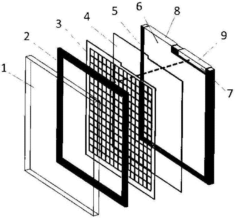
[0034] refer to figure 1 — Figure 8 , a patch-type electrowetting display module splicing screen of the present invention includes a backplane 15 and a plurality of splicing electrowetting display modules 14 arranged on the backplane 15 .

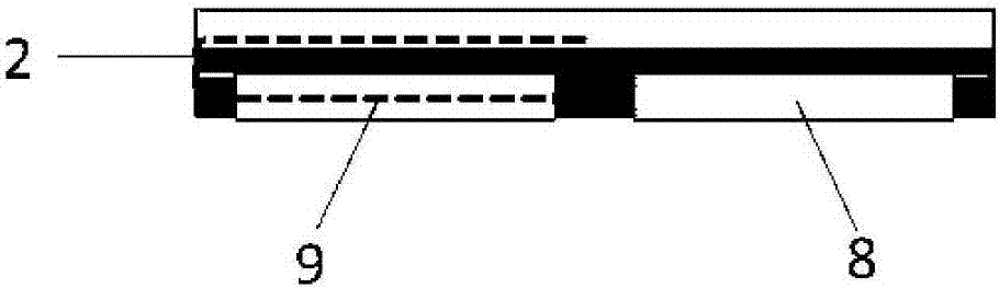
[0035] Each electrowetting display module 14 includes an upper conductive substrate 1, a conductive sealant frame 2, a pixel structure layer 3, a hydrophobic insulating layer 4, and a lower conductive substrate 5 arranged in sequence; the upper conductive substrate 1, conductive sealing frame 2, A sealed cavity is formed between the pixel structure layers 3, and the sealed cavity is filled with a conductive first fluid and a non-conductive second fluid, and the first fluid and the second fluid are in contact with each other and are immiscible; in this embodiment , the first fluid is an electrolyte solution, and the second ink. The grid surrounded by the pixel structure layer 3 is the display area.

[0036] The lower conductive substrate...


PUM


Abstract

The invention discloses a patch type electrowetting display module splicing screen and a drive control device thereof. A plurality of electrowetting display modules, a drive control device for controlling the switch display of the electrowetting display modules. The driving control device includes a driving power supply, a column scanning chip, and a row scanning chip. The first electrode seat of each column on the backplane is connected in parallel to the column port, and the second electrode seat of each row is connected in parallel to the row port. The invention can realize an outdoor display with a large size of 1-10m, and has the obvious advantages of simple driving, high flexibility, high maintainability, low cost, and low energy consumption.

Description

technical field [0001] The invention relates to the technical field of electrowetting displays, in particular to a patch-type electrowetting display module splicing screen and a drive control device thereof. Background technique [0002] Electrofluidic Display (EFD), also known as electrowetting display, is a reflective display. It generally includes an upper substrate and a lower substrate in structure. The upper substrate includes a conductive upper substrate and a packaging plastic frame, and the lower substrate includes a pixel structure. layer, hydrophobic insulating layer, and conductive lower substrate. The cavity formed by the upper and lower substrates is filled with a conductive first fluid and a non-conductive second fluid. The fluids are in contact with each other and are immiscible. The electrowetting display device produces a display effect through the relative movement of the two fluids. Electrolyte solution is usually used for conductive fluid in the prior a...

Claims


Application Information

Patent Timeline
Patent Type & Authority Patents(China)
IPC IPC(8): G02B26/00G09G3/34
Inventor 周蕤唐彪郭媛媛罗伯特·安德鲁·海耶斯周国富
Owner SOUTH CHINA NORMAL UNIVERSITY
Why Eureka
Try Eureka