Material injection gun head and refrigerator cabinet polyurethane material injection system with same

A technology of injection and injection port, which is applied in the field of polyurethane injection molding, can solve problems such as uneven filling of polyurethane, and achieve the effects of accelerating filling speed, improving production efficiency, and improving thermal insulation performance

Pending Publication Date: 2022-01-04
CHANGHONG MEILING CO LTD
View PDF0 Cites 0 Cited by
  • Summary
  • Abstract
  • Description
  • Claims
  • Application Information

AI Technical Summary

Problems solved by technology

[0005] The object of the present invention is to provide a kind of injection gun head and refrigerator cabinet polyurethane injection system with it, through the polyurethane injection system with variable material flow rate and elastic injection gun head, the problem of polyurethane caused by the large size of the box body is solved. The problem of uneven filling; solve the problem of uneven filling of polyurethane caused by the production of molds in the same row with large differences in box size

Method used


Image

  • Material injection gun head and refrigerator cabinet polyurethane material injection system with same

Examples


Embodiment 1

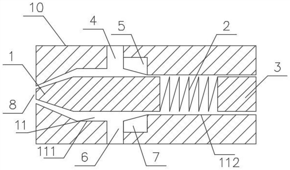
[0022] Embodiment 1, see figure 1 As shown, a filling gun head includes a gun head body 10, a cavity 11 is arranged in the gun head body 10 along its axial direction, and a discharge end of the cavity 11 is provided with a conical The material injection port 8 is equipped with a plug 1 at the injection port 8, and the end of the plug 1 is connected with a connecting rod 3 through a spring 2; the cavity 11 includes a first cylindrical cavity 111 with an inner diameter of R1 and a first cylindrical cavity with an inner diameter of R2 The second cylindrical cavity 112, the end of the second cylindrical cavity 112 communicates with the injection port 8; the connecting rod 3 and the spring 2 are located in the first cylindrical cavity 111, and one end of the connecting rod 3 runs through the first cylindrical cavity 111 and extend to the outside of the gun tip body 10, R1>R2; the gun tip body 10 is also provided with a material A inlet 4, a material A return port 5, a B material in...

Embodiment 2

[0024] Embodiment 2, an injection system based on the injection gun head of the above-mentioned embodiment 1:

[0025] It includes a program input module, an information processing module, an action module and an injection gun head; the action module connects the connecting rod 3 and drives the connecting rod 3 to expand and contract back and forth in the cavity 11; the information processing module is used to convert the program of the program input module into The electrical signal is sent to the action module.

[0026] Input and save the injection program of the Z box foaming molds through the program input module, and input the corresponding injection program for the box corresponding to each mold according to the model size characteristics; start the polyurethane injection action, when a waiting After the foamed empty box enters the corresponding mold, the elastic injection gun head is in place, and the injection starts according to the injection program corresponding to ...

Embodiment 3

[0027] Embodiment 3, the injection control method based on the injection system of the above-mentioned embodiment 2 includes:

[0028] Stp1. Input the injection volume and variable injection flow rate through the program input module;

[0029] Wherein, the variable injection flow rate is set as flow rate X1 g / s duration Y1 s, flow rate X2 g / s duration Y2s...flow rate Xng / s duration Yns, input n≥3;

[0030] Stp2. If the overall actual injection time T ≤ set the duration of each flow section ΣY, the injection will stop naturally when the injection time T is completed; if the overall injection time T > set the duration of each flow section ΣY, ΣY time is completed , continue to inject material according to the flow rate of the last stage until the injection amount is completed.


PUM


Abstract

The invention discloses a material injection gun head and a refrigerator cabinet polyurethane material injection system with the same, and relates to the technical field of polyurethane injection molding. The material injection gun head comprises a gun head body, a cavity is formed in the gun head body in the axial direction of the gun head body, a conical material injection port communicating with the cavity is formed in the discharging end of the cavity, a plug is arranged at the material injection port in a matched mode, and the tail end of the plug is connected with a connecting rod through a spring; the cavity comprises a first cylindrical cavity with the inner diameter of R1 and a second cylindrical cavity with the inner diameter of R2, and the end part of the second cylindrical cavity communicates with the material injection port; and the connecting rod and the spring are located in the first cylindrical cavity, and one end of the connecting rod penetrates through the first cylindrical cavity and extends out of the gun head body. The material injection system comprises a material injection gun head, a program input module, an information processing module and an action module. By means of the polyurethane material injection system with the variable material injection flow and the elastic material injection gun head, the problem that due to the large size of a box body, polyurethane filling is not uniform is solved.

Description

technical field [0001] The invention belongs to the technical field of polyurethane injection molding, and in particular relates to an injection gun head and a refrigerator cabinet polyurethane injection system with the same. Background technique [0002] Polyurethane foaming is an indispensable and important link in the manufacturing process of refrigerator cabinets. This process is a row of several cabinet foaming molds (generally 8 or 12, etc.), and this row of molds contains various types of cabinets. Through the high-pressure injection gun head, the polyurethane AB material is injected into the corresponding empty box body to be foamed in sequence. At present, the injection pressure and flow rate of the gun head remain unchanged. The polyurethane raw material is a two-component AB material. The AB material is injected into the empty box to be foamed through the injection gun head. At the bottom of the empty box, the AB material is injected into the back cavity under hi...

Claims


Application Information

Patent Timeline
Patent Type & Authority Applications(China)
IPC IPC(8): B29C44/42B29C44/60B29K75/00
CPCB29C44/425B29C44/60B29K2075/00B29L2031/7622
Inventor 叶小三刘鹏吴园
Owner CHANGHONG MEILING CO LTD
Why Eureka
Try Eureka