Paper type collecting device

It is a paper-based and accumulative technology, which is applied in the directions of transportation and packaging, sending objects, and thin material processing. It can solve the problems of complicated control content and difficult deceleration, and achieve the effects of reducing rebound, preventing scatter, and reducing speed.

Active Publication Date: 2011-08-31
FUJITSU FRONTECH LTD
View PDF6 Cites 13 Cited by
  • Summary
  • Abstract
  • Description
  • Claims
  • Application Information

AI Technical Summary

Problems solved by technology

[0013] However, in Patent Document 1, it is necessary to arrange sensors at multiple positions, detect the speed of banknotes at each position, etc. each time, and adjust the speed of the conveyor belt according to the detected value, and the control content is complicated.
[0014] In addition, in Patent Document 2, the feeding speed is reduced by passing the banknotes through the space between the deceleration plates;

Method used


Image

  • Paper type collecting device
  • Paper type collecting device
  • Paper type collecting device

Examples


no. 1 approach

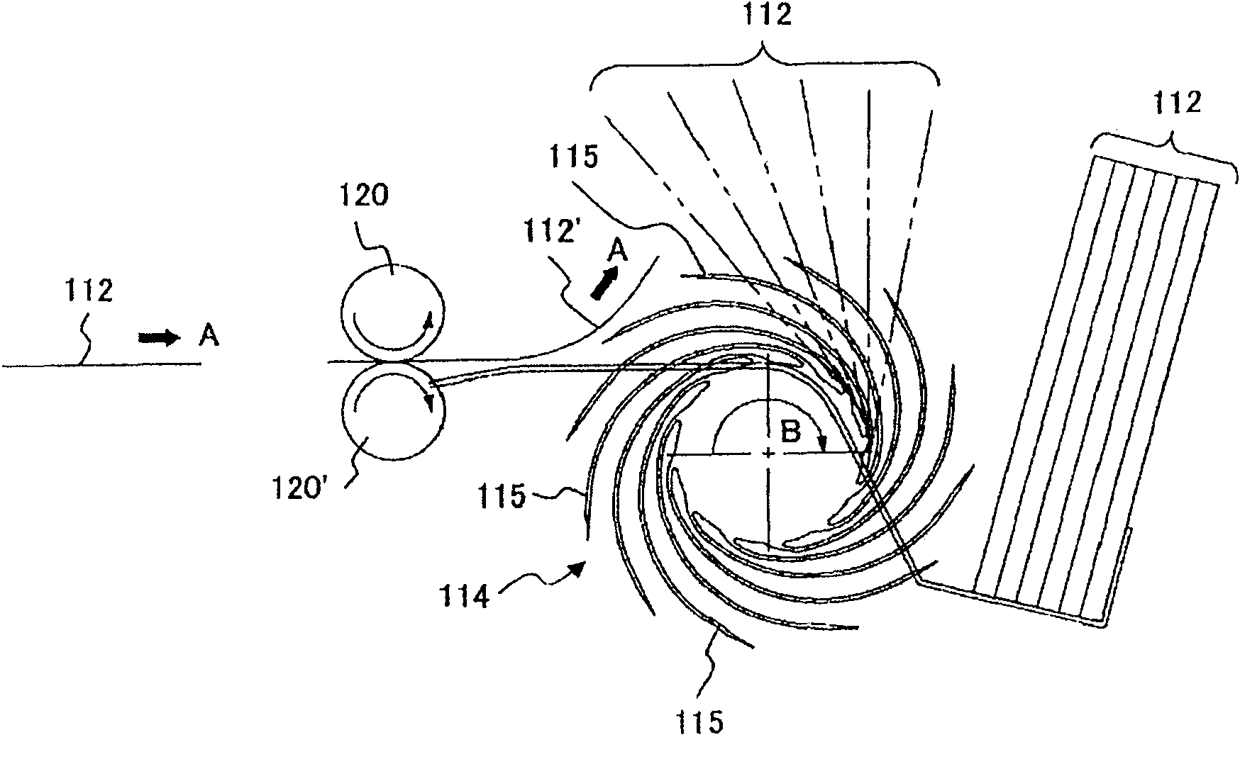
[0042] image 3 It is a side view of the sheet stacking device of the first embodiment, Figure 4A is the front view of the impeller, Figure 4B and Figure 4C is its side view.

[0043] exist image 3 Among them, the paper stacking device 10 is a device that vertically accommodates bills, checks, securities, and the like as paper bills, for example, paper bills 12 .

[0044] The paper stacking device 10 includes: an impeller 14 having a plurality of blades 15 on the outer peripheral surface, and the impeller 14 accommodates the banknotes 12 between adjacent blades 15, 15 and rotates and conveys them in the direction of the arrow F; The accumulating portion 16 accumulates the banknotes 12 conveyed by the impeller 14 ;

[0045] In addition, the banknotes 12 are continuously supplied to the impeller 14 one by one at a constant speed in a fixed direction by the transport roller pair 20, 20'.

[0046] Furthermore, the banknotes 12 are conveyed one by one while being rotated by...

no. 2 approach

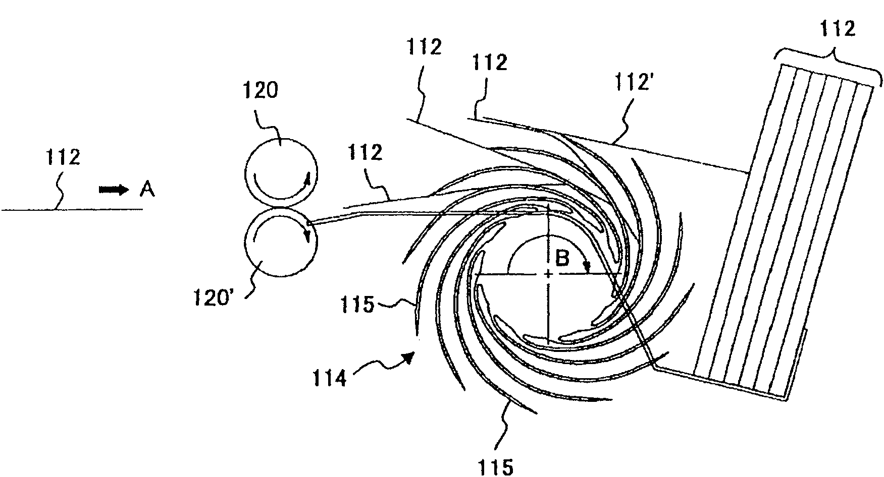
[0082] Figure 7A It is a front view of the impeller of the sheet stacking device of the second embodiment, Figure 7B is its side view. In addition, the same code|symbol is attached|subjected to the same or equivalent part as 1st Embodiment, and the description is abbreviate|omitted.

[0083] In this embodiment, if Figure 7A and Figure 7B As shown, a cylindrical roller 30 fixed to the drive shaft 22 is arranged between a pair of symmetrical first and second impellers 14A, 14A.

[0084] In this way, even when the roller 30 is disposed between the first and second impellers 14A, 14A, an upward convex crease 24 can be formed at the center of the banknote 12 in the width direction (see Figure 7B ). Thereby, the frictional force between the banknote 12 and blade|wing 15A, 15A etc. increases, and it can prevent that the banknote 12 detached from the blade wheel 14 and scattered during rotary conveyance.

[0085] In this embodiment, if Figure 7A As shown, the radius of the ...

no. 3 approach

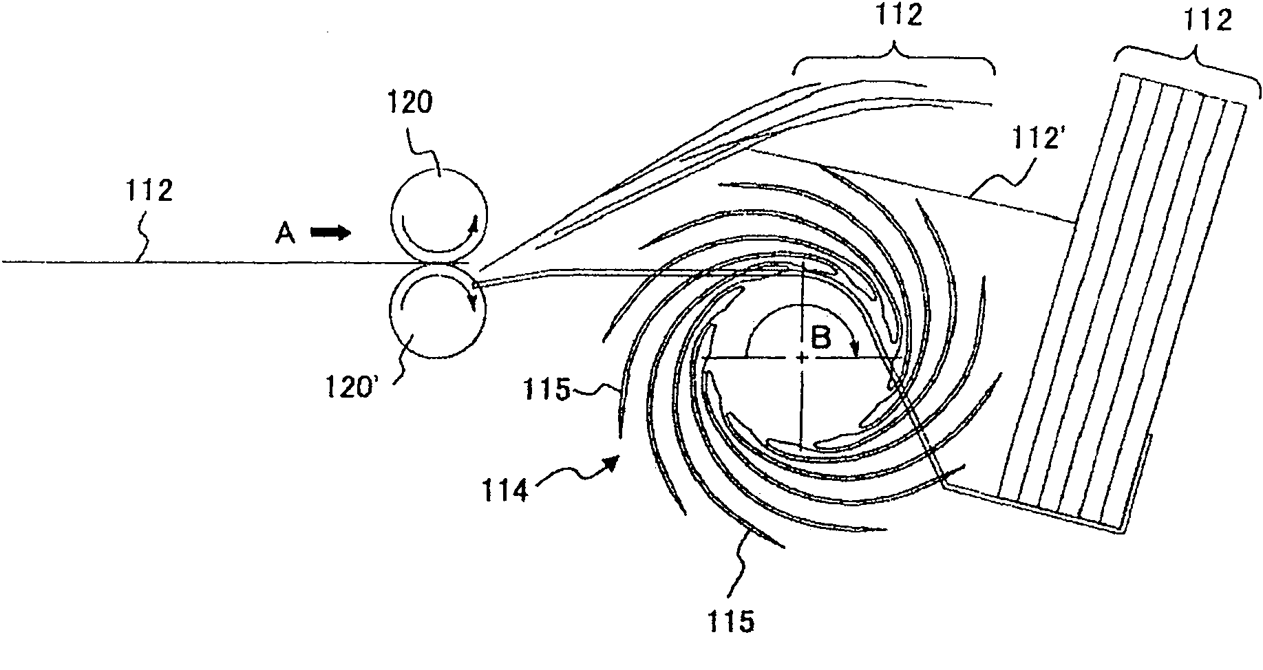
[0095] Figure 8A It is a front view of the impeller of the sheet stacking device of the third embodiment, Figure 8B is its side view. In addition, the same code|symbol is attached|subjected to the same or equivalent part as 1st Embodiment, and the description is abbreviate|omitted.

[0096] In this embodiment, if Figure 8A As shown, protrusions 32 are formed on the outer surfaces of the blades 15A, 15A of the respective first and second impellers 14A, 14A.

[0097] In this embodiment, in Figure 8A Among them, the protruding portion 32 is formed when the banknote 12 comes into contact with the tip g of one blade 15A-1 of the adjacent blades of the first and second impellers 14A, 14A when the banknote 12 comes into contact with the other blade 15A-2. The contact point h.

[0098] In addition, in this embodiment, although the case where the protrusion part 32 was formed in the same position as the contact point h was demonstrated, it is not limited to this. For example,...


PUM


Abstract

The invention provides a paper type collecting device, which can reliably receive bank notes between adjacent blades, prevent bank notes collected between adjacent blades from scattering and can evenly laminate bank notes in order in a collecting part. A paper type collecting device (10) comprises an impeller (14) which is provided with a plurality of blades (15) at peripheral surfaces and receive bank notes (12) between adjacent blades and conveys bank notes by rotation, a collecting part (16) which collects bank notes conveyed by the impeller, and a guiding component (18) which abuts against the conveying top end of the bank notes to guide the bank notes to the collecting part. The impeller comprises a first impeller (14A) and a second impeller (14A') in symmetry which are fixed to a driving shaft (22) with a interval narrower than the width of the bank note, and a third impeller (14B). The third impeller is in the shape as the first and the second impeller, and is fixed to the driving shaft between the first and the second impellers. The third impeller is disposed in a manner that the rotation phase of the third impeller staggers with that of the first and the second impellers.

Description

technical field [0001] The present invention relates to a paper stacking device that transports paper such as banknotes, checks, and securities by means of an impeller and stacks them in a stacking section. Background technique [0002] Such a paper stacking device is, for example, a device that stacks paper sheets (for example, banknotes) in a stacking section in order to bundle paper sheets (for example, banknotes) in a predetermined number (for example, 100). This paper stacking device receives the banknotes conveyed sequentially and continuously between adjacent blades, rotates and conveys them, and drops the banknotes to the stacking portion to be stacked. [0003] Figure 1A ~ Figure 1C A conventional example of the sheet stacking device when banknotes are stored vertically (storage so that the surface of the banknote is substantially parallel to the direction of gravity) is shown. [0004] like Figure 1A As shown, the banknote 112 supplied in the direction of arrow...

Claims


Application Information

Patent Timeline
Patent Type & Authority Applications(China)
IPC IPC(8): B65H29/20
CPCB65H29/40B65H29/70B65H2301/51214
Inventor 玉桥知之浜地宣之寺岛健太郎
Owner FUJITSU FRONTECH LTD
Why Eureka
Try Eureka