
Negotiable video data transmission mode

A technology for video data transmission and video surveillance, applied in closed-circuit television systems, electrical components, selective content distribution, etc., can solve problems such as communication failures, and achieve the effect of solving communication failures

Active Publication Date: 2011-08-31
GUANGDONG ELECTRIC POWER SCI RES INST ENERGY TECH CO LTD
View PDF5 Cites 0 Cited by
  • Summary
  • Abstract
  • Description
  • Claims
  • Application Information

AI Technical Summary

Problems solved by technology

[0003] The purpose of the present invention is to provide a negotiable video data transmission mode. The present invention flexibly allocates video data transmission ports by negotiating video data ports, and solves the problem of communication failure caused by ports being occupied

Method used


Image

  • Negotiable video data transmission mode
  • Negotiable video data transmission mode
  • Negotiable video data transmission mode

Examples


Embodiment Construction

[0012] The present invention will be further described below in conjunction with the accompanying drawings and embodiments, but not as a basis for limiting the present invention.

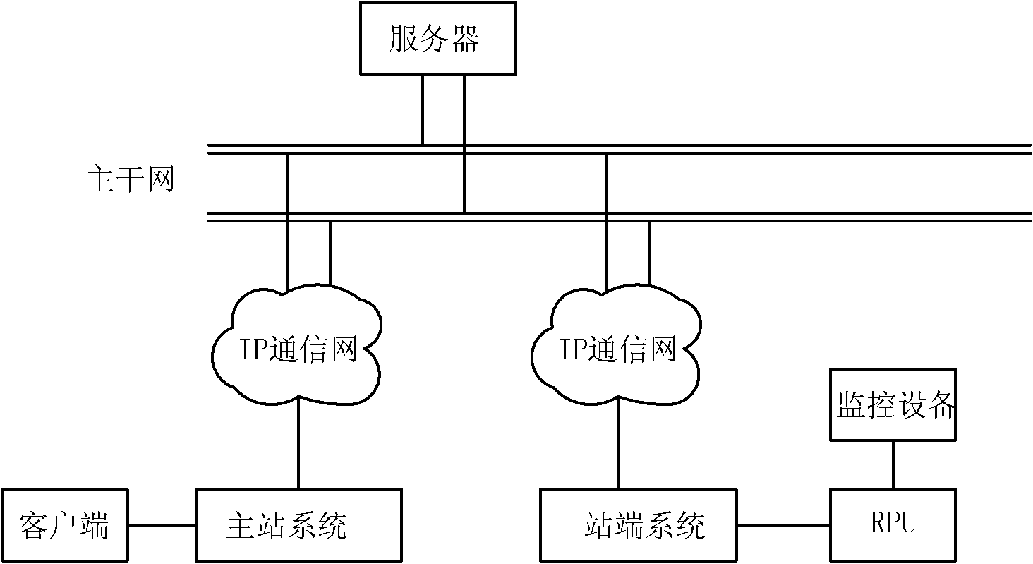
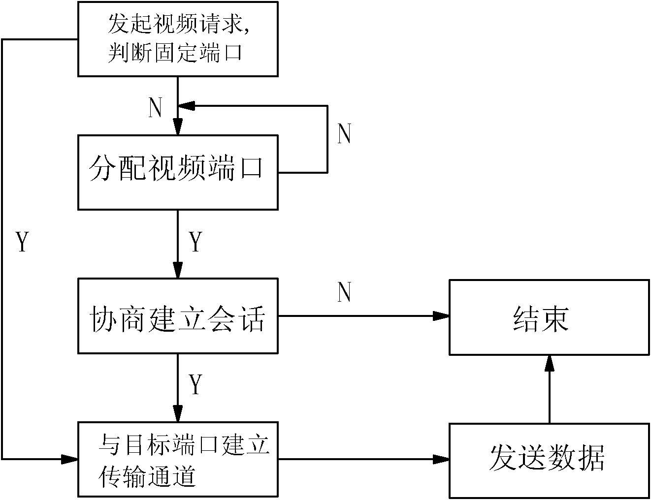
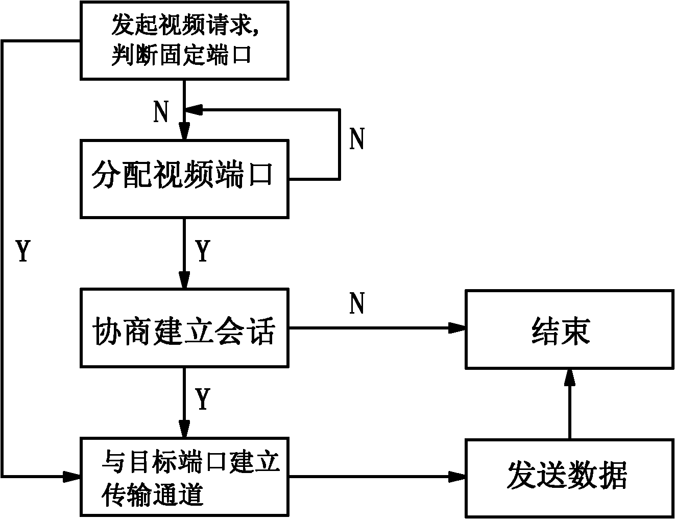
[0013] Embodiment: negotiable video data transmission mode, as attached figure 1 As shown, it is applied to the video surveillance system of the power grid, including the client terminal for managing video surveillance information, the station-side system for performing video surveillance, the network system connecting the client terminal and the station-side system, and processing the transmission data between the client terminal and the station-side system server; the station-end system includes monitoring equipment and station-end processing units, such as attached figure 2 As shown, the method includes the following steps;

[0014] (a), the client initiates a video transmission request to the server; the server judges whether the fixed video communication port of the station-side processing un...


PUM


Abstract

The invention discloses a negotiable video data transmission mode. When fixed video data communication ports of a client and a remote process unit are occupied, a server flexibly allocates idle transmission ports, so the problems of communication failures caused by the occupation of the port are solved.

Description

technical field [0001] The invention relates to a negotiable video data transmission mode and belongs to the field of power grid security communication. Background technique [0002] With the continuous expansion of the grid scale, the operating workload of the video surveillance system applied to the grid is increasing, and the existing video data transmission methods are also facing severe challenges. For example, in order to cope with the expansion of the grid scale, Guangdong Power Grid took the lead in adopting a video surveillance system with a provincial, regional and station-level three-level structure in the power industry. The station-side system (full name substation video and environment monitoring station-side system) is used to monitor the on-site video and environmental information of the substation, and upload the information to the regional master station; including video monitoring equipment and real-time processing, transmission, storage and other function...

Claims


Application Information

Patent Timeline
IPC IPC(8): H04N7/18H04N21/65
Inventor 刘之尧高新华谢善益梁晓兵高雅张飞
Owner GUANGDONG ELECTRIC POWER SCI RES INST ENERGY TECH CO LTD
Learn More