Assembled drainage canal of debris flows and construction method thereof

A technology for draining guide troughs and debris flow, applied in water conservancy projects, artificial waterways, embankments, etc., can solve problems such as being easily affected by construction seasons, large site environmental damage, and difficult transportation of construction materials, so as to shorten the construction period and save construction period , Solve the effect of mass transportation

Inactive Publication Date: 2011-09-07
INST OF MOUNTAIN HAZARDS & ENVIRONMENT CHINESE ACADEMY OF SCI
View PDF5 Cites 10 Cited by
  • Summary
  • Abstract
  • Description
  • Claims
  • Application Information

AI Technical Summary

Problems solved by technology

[0004] The purpose of the present invention is to address the deficiencies of the prior art, and to provide a fast construction, high-efficiency Assembl

Method used


Image

  • Assembled drainage canal of debris flows and construction method thereof
  • Assembled drainage canal of debris flows and construction method thereof
  • Assembled drainage canal of debris flows and construction method thereof

Examples


Embodiment 1

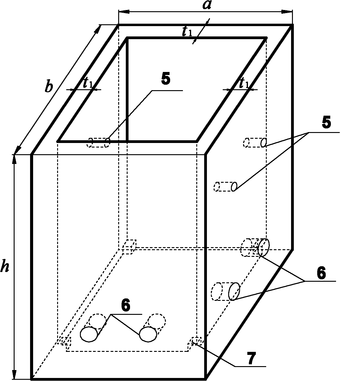
[0033] Such as figure 1 , figure 2 , image 3 , Figure 5 shown. The drainage area of ​​a debris flow ditch is 5.6km 2 , in order to control debris flow disasters, it is planned to set up 5 Gufang, 1 sand dam and 700m drainage channel in the middle of the basin. For the row guide groove, the following construction methods are adopted:

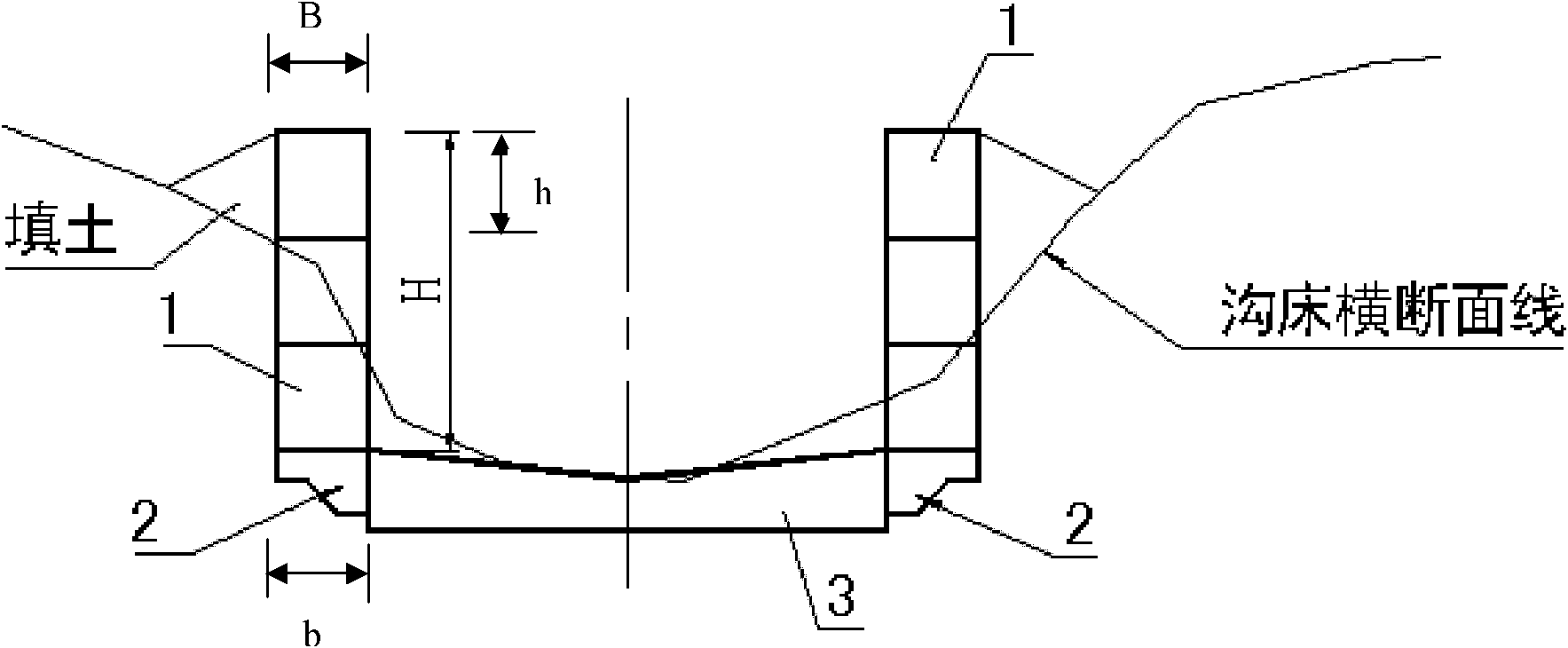
[0034] The first step is to plan and design the bottom of the trench to be a horizontal through-type rib sill according to the situation of the debris flow ditch. B is 1.0m. Since the side wall height H of the row of guide troughs is less than or equal to 8.0m, it is proposed to adopt the assembled debris flow drainage trough of the present invention. The assembled debris flow drainage trough includes several prefabricated reinforced concrete rectangular boxes 1 vertically and horizontally connected, distributed in a single row along the direction of the trough, and forming the main body of the side wall of the trough. The top surface o...

Embodiment 2

[0043] Such as figure 1 , figure 2 , Figure 4 , Figure 5 shown. The same as the first embodiment will not be repeated, the difference is:

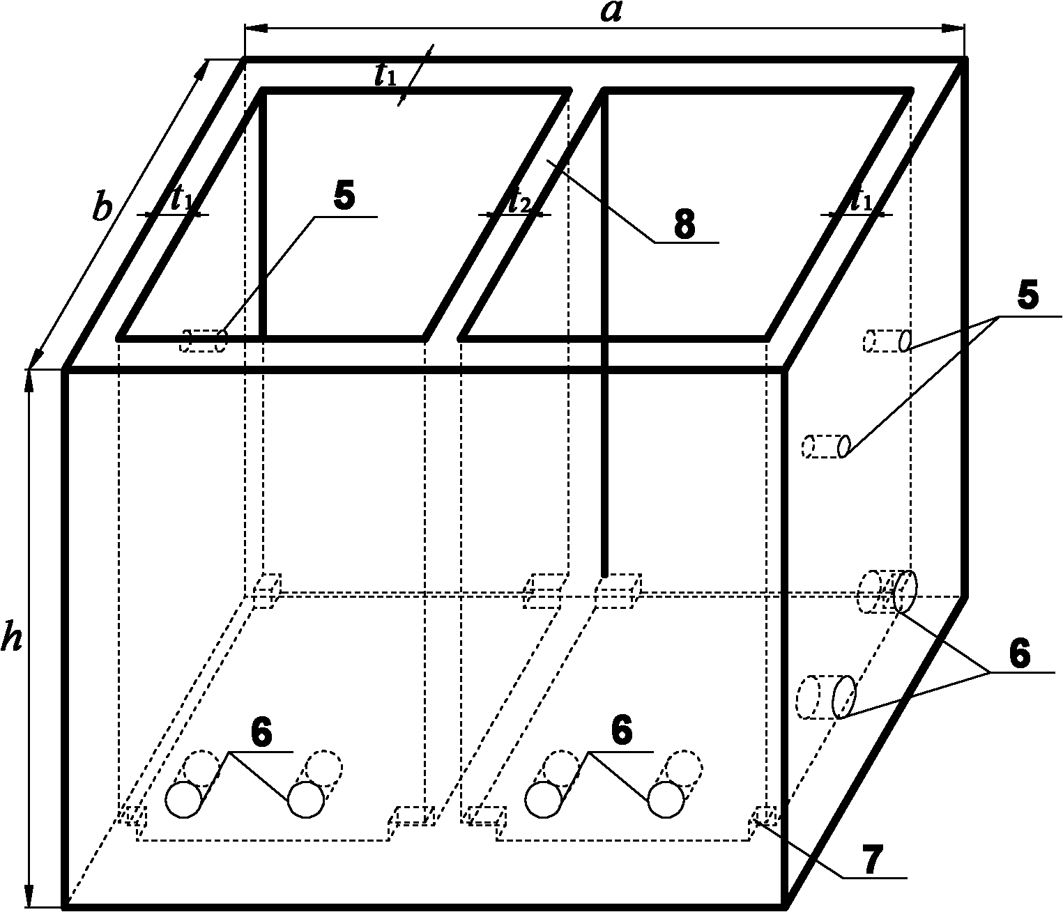
[0044] The first step, for the debris flow ditch basin area of ​​20.0km 2 , the planning and design of the bottom of the trough is a fully lined floor 4. Debris flow drainage trough with an anticline side wall, the height H of the side wall of the trough is 8.0m, and the top width B of the side wall of the trough is 1.5m. Since the side wall height H of the row of guide troughs is less than or equal to 8.0m, it is proposed to adopt the assembled debris flow drainage trough of the present invention. According to the planned spatial dimensions of the side walls of the guide trough, the geometric dimensions of the prefabricated rectangular box 1 are planned:

[0045] ①According to the height H of the side wall of the guide trough being an integer multiple n1 of the height h of the rectangular box 1, it is initially proposed that n1 i...


PUM

PropertyMeasurementUnit
Heightaaaaaaaaaa
Diameteraaaaaaaaaa
Thicknessaaaaaaaaaa

Abstract

The invention discloses an assembled drainage canal of debris flows and a construction method thereof. The drainage canal comprises a drainage canal bottom and drainage canal side walls at two sides of the drainage canal, wherein the drainage canal side walls respectively comprise a side-wall foundation and a side-wall main body on the side-wall foundation; a plurality of prefabricated rectangular reinforced concrete rectangular boxes are connected vertically and horizontally and distributed in a single row along the direction of the drainage canal, thus forming the side-wall main body; and the top surface of each rectangular box is opened, the other five surfaces of each rectangular box are closed, and the inside of each rectangular box is filled with soils. Compared with the prior art, the quick assembly characteristic of the rectangular boxes is utilized, so that the rectangular boxes can be prefabricated in an area which is far away from the drainage canal, which is conducted together with the construction of the side-wall foundation of the drainage canal and the drainage canal bottom synchronously, thereby shortening the construction period and reducing the influences on environments around the drainage canal scene. The soils existing in channels can be loaded in the rectangular boxes directly, thereby solving the problem that construction materials are transmitted massively. Compared with the traditional drainage canal, the assembled drainage canal has the advantages that the project investment can be saved by 20-50% and the construction period can be saved by 20-80%.

Description

technical field [0001] The invention relates to a mud-rock flow prevention technology, in particular to an assembled mud-rock flow drainage channel based on a rectangular box body for quickly assembling side walls and a construction method thereof. Background technique [0002] Debris flow disaster is one of the main types of geological disasters in my country. With the development of the mountainous economy and the deepening of the western development, the demand for debris flow control is becoming more and more vigorous. As one of the main types of debris flow prevention and control engineering, drainage channels are widely used in debris flow control. [0003] At present, the debris flow drainage channel mainly adopts masonry structure or concrete structure, followed by reinforced concrete structure, and its construction method is still on-site construction. There are following defects in the guide trough of the existing structure and its construction method: First, due...

Claims


Application Information

Patent Timeline
IPC IPC(8): E02B5/00E02B5/02E02B3/10E02B3/12E02B3/14E01F7/04
Inventor 陈晓清崔鹏游勇李德基
Owner INST OF MOUNTAIN HAZARDS & ENVIRONMENT CHINESE ACADEMY OF SCI
Why Eureka
Try Eureka