Lead sag monitoring device

A technology for monitoring device and wire sag, which is applied in the direction of measuring device, optical device, instrument, etc., can solve the problems of large error, the temperature of wire is easily affected by environmental factors, and it is difficult to find problems, so as to improve the measurement accuracy and avoid Effects of environmental factor error and efficiency improvement

Inactive Publication Date: 2011-09-07
SHENZHEN CITY WEIKEFENGYUN ELECTRIC AUTOMATION EQUIP
View PDF4 Cites 6 Cited by
  • Summary
  • Abstract
  • Description
  • Claims
  • Application Information

AI Technical Summary

Problems solved by technology

However, this method has obvious shortcomings, mainly because the temperature of the wire is easily affected by environmental factors, and the calculated error is also relatively large, making it difficult to find problems in time

Method used


Image

  • Lead sag monitoring device
  • Lead sag monitoring device
  • Lead sag monitoring device

Examples


Embodiment Construction

[0025] Specific embodiments of the present invention will be described in detail below in conjunction with the accompanying drawings.

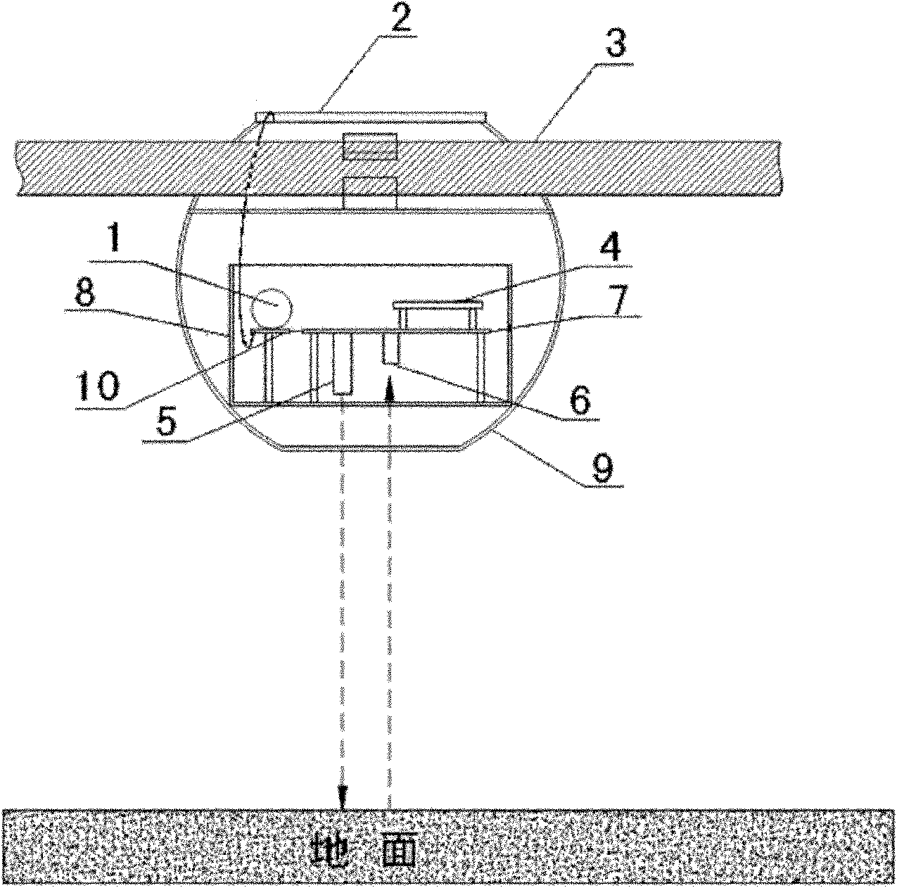
[0026] A wire sag monitoring device, including a semiconductor laser 5, a photoelectric receiver 6, a laser drive and receiving amplification counting circuit board 7, is characterized in that:

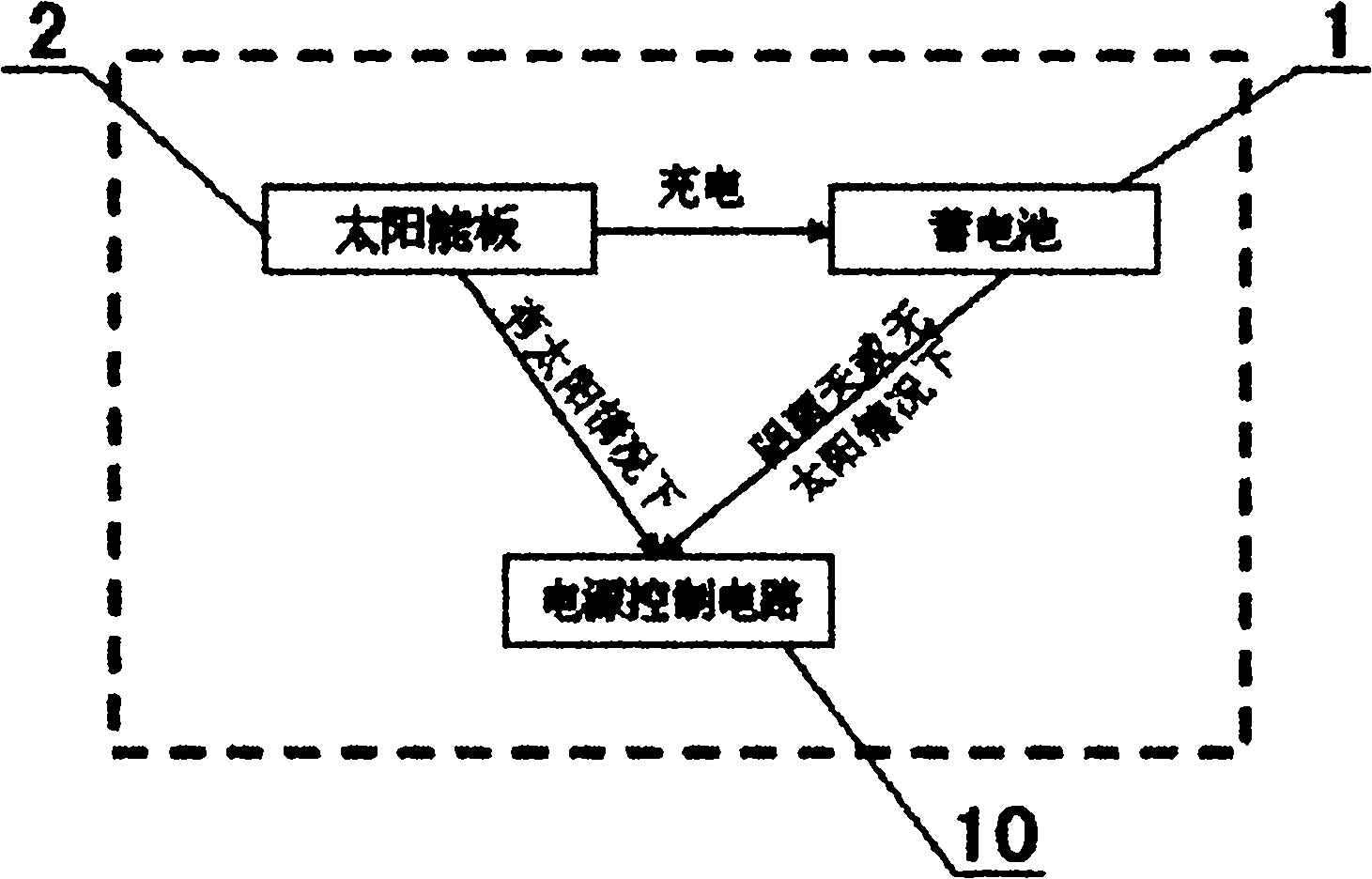
[0027] The laser driving circuit and the receiving, amplifying and counting circuit board 7 are fixedly installed in the first installation box 8 .

[0028] The semiconductor laser 5 is installed in the first installation box 8 through a screw card, and is connected with the laser driving and receiving amplification counting circuit board 7 for emitting laser light.

[0029] The photoelectric receiver 6 is mounted on the laser driving circuit and the receiving amplification counting circuit board 7 for receiving reflected laser light.

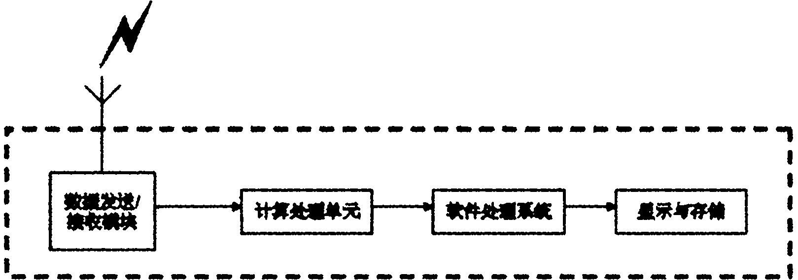
[0030] The wireless communication module 4 is installed on the laser driving circuit and the receiving, amplifying ...


PUM


Abstract

The invention discloses a lead sag monitoring device. A laser driving circuit and receiving, amplifying and counting circuit board is fixedly arranged in a first mounting box; a semiconductor laser device is arranged in the first mounting box through a screw clamp and connected with the laser driving and receiving, amplifying and counting circuit board; a photoelectric receiver is arranged on the laser driving circuit and receiving, amplifying and counting circuit board; a wireless communication module is arranged on the laser driving circuit and receiving, amplifying and counting circuit board; a storage battery is connected with a power supply control circuit board through a power wire; a solar panel is connected with the power supply control circuit board through a power wire; the power supply control circuit board is connected with the laser driving circuit and receiving, amplifying and counting circuit board and used for supplying power to the whole device; and the whole first mounting box is fixedly arranged in a second mounting box, and the second mounting box is arranged on a lead through a metal clip. The device is not affected by environmental factors, has high precision, and can remotely and automatically monitor the sag of the lead.

Description

technical field [0001] The present invention relates to an electric power monitoring device, more specifically to a wire vertical arc monitoring device. Not affected by environmental factors, with high precision, it can carry out remote automatic monitoring of wire sag. Background technique [0002] Transmission lines are an important part of the power system. At present, my country's power shortage is serious. The transmission capacity of transmission lines in many areas cannot meet the growing demand for electricity, and they are forced to limit power. According to the statistics of the State Grid Corporation of my country, in the first half of 2010, there were a total of 757,000 power cuts in China, and the power loss was 19.453 billion kWh. This not only seriously affected people's daily production and life, but also caused immeasurable economic losses. For this reason, in order to meet the demand for electricity in some areas, the amount of wire transmission is increa...

Claims


Application Information

Patent Timeline
Patent Type & Authority Applications(China)
IPC IPC(8): G01B11/02H02N6/00
Inventor 李开元
Owner SHENZHEN CITY WEIKEFENGYUN ELECTRIC AUTOMATION EQUIP
Why Eureka
Try Eureka