
Method and device for detecting defects and failures of high-speed rail based on vibration signals

A technology of vibration signal and detection method, which is applied in processing the response signal of detection and analyzing solids using sonic/ultrasonic/infrasonic waves, which can solve problems such as affecting the efficiency of train operation.

Inactive Publication Date: 2011-09-07
HARBIN INST OF TECH
View PDF2 Cites 44 Cited by
  • Summary
  • Abstract
  • Description
  • Claims
  • Application Information

AI Technical Summary

Problems solved by technology

[0004] The purpose of the present invention is to solve the problem that the existing measuring equipment will seriously affect the train operation efficiency when detecting the damage of the high-speed rail rail, and provides a method and device for detecting damage to the high-speed rail rail based on vibration signals

Method used


Image

  • Method and device for detecting defects and failures of high-speed rail based on vibration signals
  • Method and device for detecting defects and failures of high-speed rail based on vibration signals
  • Method and device for detecting defects and failures of high-speed rail based on vibration signals

Examples


specific Embodiment approach 1

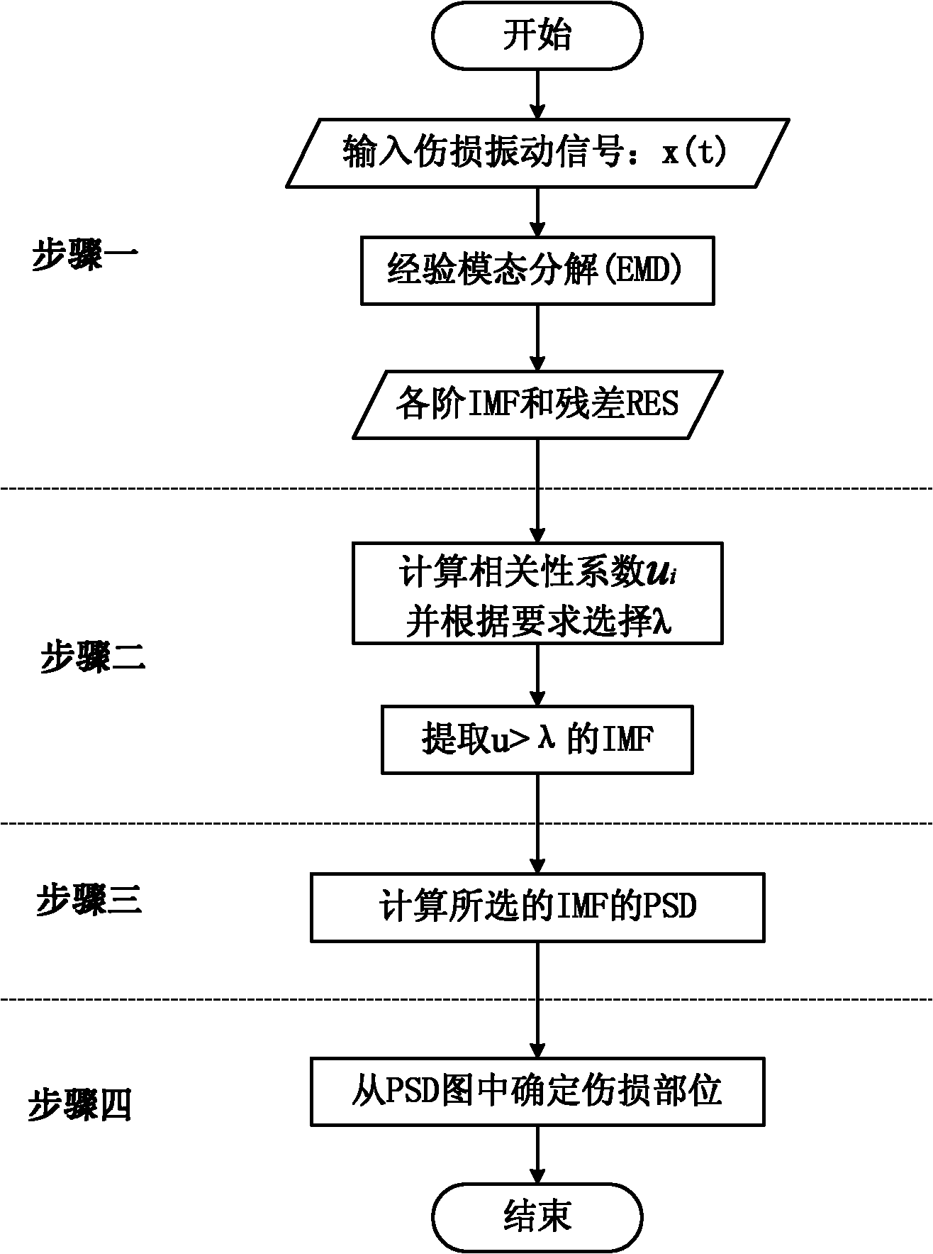
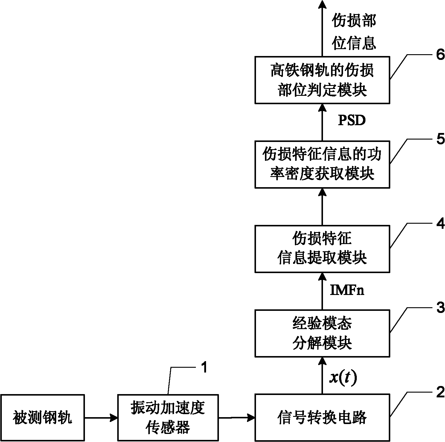
[0026] Specific implementation mode one: the following combination figure 1 , figure 2 and Figure 5 To illustrate this embodiment, the present invention adopts a new high-speed train damage detection method based on vibration signal feature extraction, aiming at the fact that the existing flaw detection technology and flaw detection mechanism cannot meet the flaw detection requirements of high-speed railways. By establishing a corresponding track damage detection sensor network along the railway line, the rail vibration signal is measured, and the signal is preprocessed and sent to the flaw detection vehicle or a specific information center; after the flaw detection vehicle or information center receives the signal, it uses the empirical model State decomposition (EMD) decomposes the received vibration signal to obtain the corresponding internal solid mode function (IMF). The obtained IMF components of each order contain the characteristic information of rail damage (the ch...

specific Embodiment approach 2

[0037] Specific implementation mode two: the following combination Figure 4 Illustrate this embodiment, this embodiment will further explain Embodiment 1: in the step 1, collect the vibration signal of the high-speed rail rail by the vibration acceleration sensor, the vibration acceleration sensor is arranged on the rail bottom upper surface of the high-speed rail rail, and the distance from the rail bottom outer edge d In terms of distance, the value range of d is 18mm-20mm.

specific Embodiment approach 3

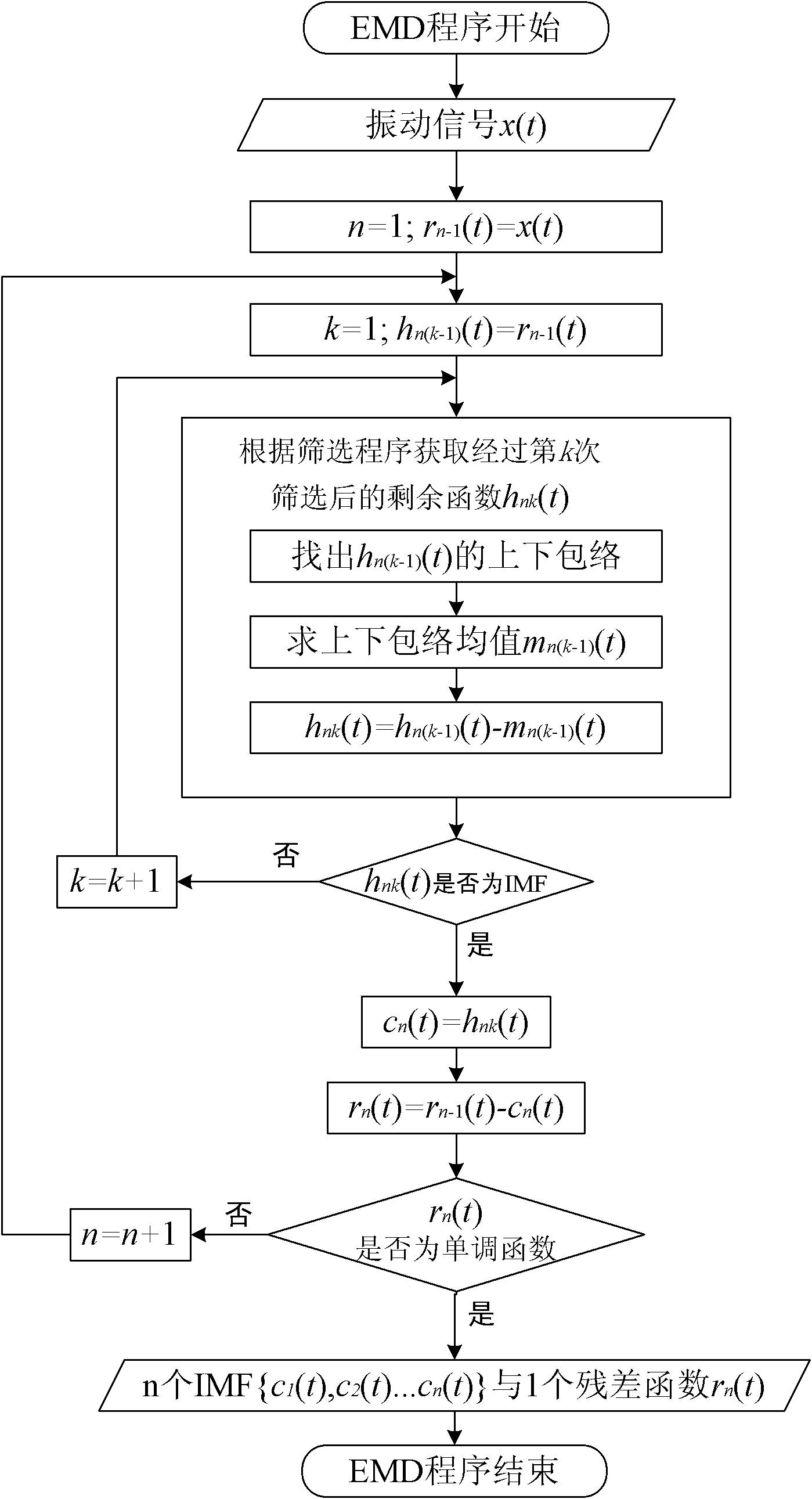
[0038] Specific implementation mode three: the following combination image 3 Describe this embodiment, this embodiment will further explain Embodiment 1: the process of obtaining n IMF components and a residual in step 1 is:

[0039] Set the input damage vibration signal as x(t), t=1, 2,..., N,

[0040] Step 11, IMF decomposition process initialization: n=1, and satisfy the relation r n-1 (t)=x(t) holds, where r n-1 (t) is the trend function after the (n-1)th decomposition;

[0041] Step 12: Initialize the screening process, k=1, and satisfy the relation hn(k-1) (t)=r n-1 (t) holds, where h n(k-1) (t) is the residual function after the (k-1)th screening in the nth empirical mode decomposition;

[0042] Step 13. Obtain the remaining function h after the kth screening according to the screening program nk (t);

[0043] Step 14, using the standard deviation criterion to judge the remaining function h obtained in step 13 nk (t) Whether the condition of the intrinsic mode ...


PUM


Abstract

The invention discloses a method and device for detecting defects and failures of a high-speed rail based on vibration signals, belonging to the technical field of railway safety monitoring and protection. The invention solves the problem that the operating efficiency of a train is seriously influenced when a current measurement device detects the defects and failures of the high-speed rail. The method comprises the following steps of: 1, acquiring a vibration signal of the high-speed rail by a vibration acceleration transducer, carrying out experience mode decomposition on the vibration signal, and acquiring n IMF (Intrinsic Mode Function) components and one residual error; 2, calculating a correlation coefficient ui (i=1, 2, ......, n) of the n IMF components acquired in the step 1 and the acquired vibration signal, and selecting the IMF component, the correlation coefficient ui of which is larger than a threshold lambda, as defect and failure feature information IMF; 3, respectively calculating power spectral density of the defect and failure feature information IMF acquired in the step 2; and 4, determining defect and failure parts of the high-speed rail according to the power spectral density of the defect and failure feature information IMF acquired in the step 3, and finishing the detection of the defects and failures of the high-speed rail.

Description

technical field [0001] The invention relates to a vibration signal-based high-speed rail rail damage detection method and device, belonging to the technical field of railway safety monitoring and protection. Background technique [0002] Railway is the main artery of transportation and plays a very important role in the development of national economy. With the continuous improvement of train speed and the increase of density and load, especially the rapid development of high-speed rail, new challenges are posed to the existing railway rail flaw detection methods. [0003] Existing railway rail flaw detection is based on a large-scale rail flaw detection vehicle, supplemented by a small rail flaw detector. At present, the speed of domestic rail flaw detection vehicles is very low (generally 50-80 km / h), but the speed of high-speed rail is between 250-350 km / h. When these equipments detect rails, they will occupy the high-speed rail line, seriously affect the efficiency of ...

Claims


Application Information

Patent Timeline
Patent Type & Authority Applications(China)
IPC IPC(8): G01N29/04G01N29/12G01N29/50
Inventor 王艳章欣沈毅
Owner HARBIN INST OF TECH
Learn More