
Method and device for determining shielding condition of camera head

A camera and video camera technology, applied in image communication, image analysis, image data processing and other directions, can solve problems such as monitoring failure, and achieve the effect of avoiding monitoring failure and facilitating timely maintenance.

Active Publication Date: 2011-09-07
NETPOSA TECH
View PDF1 Cites 30 Cited by
  • Summary
  • Abstract
  • Description
  • Claims
  • Application Information

AI Technical Summary

Problems solved by technology

[0003] Embodiments of the present invention provide a method and device for determining that the camera is blocked, so as to solve the technical problem that the camera is blocked and cause monitoring failure

Method used


Image

  • Method and device for determining shielding condition of camera head
  • Method and device for determining shielding condition of camera head
  • Method and device for determining shielding condition of camera head

Examples


Embodiment Construction

[0062] In order to enable those skilled in the art to better understand the solutions of the embodiments of the present invention, the embodiments of the present invention will be further described in detail below in conjunction with the drawings and implementations.

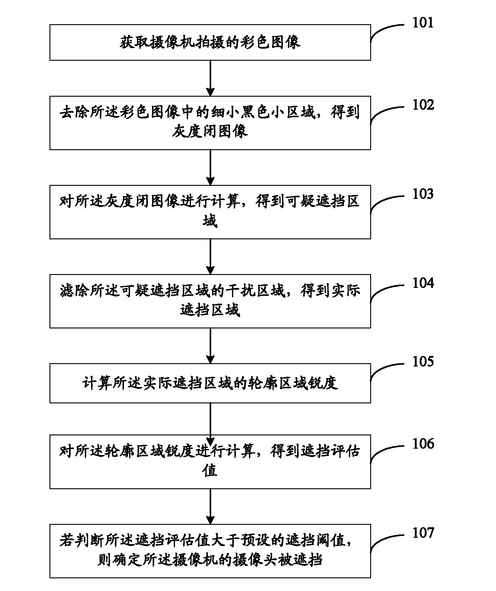
[0063] see figure 1 , the present invention provides a flow chart of a method for determining that the camera is blocked; the method includes:

[0064] Step 101: Acquire a color image captured by a camera; that is, acquire a color image captured by a camera.

[0065] Step 102: removing small black areas in the color image to obtain a grayscale closed image;

[0066] Step 103: Calculate the grayscale closed image to obtain suspicious occlusion areas;

[0067] Step 104: Filter out the interference area of ​​the suspicious occlusion area to obtain the actual occlusion area;

[0068] Step 105: Calculate the sharpness of the contour area of ​​the actual occlusion area;

[0069] Step 106: Calculate the sharpness o...


PUM


Abstract

The invention relates to a method and device for determining the shielding condition of a camera head. The method comprises the following steps of: acquiring a color image shot by a camera; removing small tiny black regions in the color image to obtain a grey-scale closed image; calculating the grey-scale closed image to obtain a suspicious shielding region; filtering an interference region of the suspicious shielding region to obtain an actual shielding region; calculating the outline region acuity of the actual shielding region; calculating the outline region acuity to obtain a shielding evaluation value; and determining that the camera head of the camera is shielded if the shielding evaluation value is judged to be larger than a preset shielding threshold value. The invention aims to solve the technical problem of monitoring failure caused by the shielded camera head.

Description

technical field [0001] The invention relates to the technical field of monitoring, in particular to a method and device for determining that a camera is blocked. Background technique [0002] With the advancement of the "Safe City" project, the number of cameras in each city is increasing day by day, ranging from a few thousand to tens of thousands to hundreds of thousands. Especially for cameras that work outdoors for a long time, the lens of the camera may be partially blocked by objects such as sludge, affecting normal observation, or may be blocked maliciously by humans. If this situation cannot be discovered by the monitoring personnel in time, it will lead to monitoring failure. Contents of the invention [0003] Embodiments of the present invention provide a method and device for determining that a camera is blocked, so as to solve the technical problem that monitoring fails due to the blocked camera. [0004] In order to solve the above technical problems, an embo...

Claims


Application Information

Patent Timeline
Patent Type & Authority Applications(China)
IPC IPC(8): G06T7/00H04N5/225
Inventor 孙余顺
Owner NETPOSA TECH
Learn More