Method for identifying modal parameters of transformer coil

A technology of modal parameter identification and transformer winding, which is applied in the direction of instruments, measuring electrical variables, measuring devices, etc., can solve problems such as accidents, insulation damage, and winding vibration aggravation

Inactive Publication Date: 2013-08-28
SHANGHAI JIAO TONG UNIV
View PDF3 Cites 32 Cited by
  • Summary
  • Abstract
  • Description
  • Claims
  • Application Information

AI Technical Summary

Problems solved by technology

[0003] After the transformer suffers a sudden short circuit, the huge short-circuit electromotive force makes the winding vibration intensify, so that the winding may be loosened or deformed first
A large number of experimental studies have shown that the deformation of transformer windings has a cumulative effect. If the looseness or deformation cannot be detected and repaired in time, then after the looseness or deformation of the transformer accumulates to a certain extent, the short-circuit resistance of the transformer will be greatly reduced. A small inrush current can also cause a large accident
On the one hand, the deformation of the winding will lead to a decrease in the mechanical resistance to short-circuit current impact, and on the other hand, it will also cause the local insulation distance inside the coil to change, causing local insulation weak points to appear. Inter-turn or turn-to-turn short circuit leads to transformer insulation breakdown accident, or partial discharge caused by the increase of local field strength, the insulation damage part will gradually expand, and finally lead to transformer insulation breakdown accident and cause further expansion of the situation
In addition, when the excitation frequency of the short-circuit electromotive force is close to the natural frequency of the winding, resonance may occur, which will lead to serious deformation of the winding, insulation damage, and even axial instability resulting in winding collapse

Method used


Image

  • Method for identifying modal parameters of transformer coil
  • Method for identifying modal parameters of transformer coil
  • Method for identifying modal parameters of transformer coil

Examples


Embodiment Construction

[0082] The method for diagnosing the running state of the transformer winding of the present invention will be further described in detail below in conjunction with the drawings and embodiments.

[0083] In this embodiment, a 10kV transformer winding is monitored and diagnosed according to the following steps:

[0084] (1) An exciter is placed on the transformer winding, and the 20kHz white noise signal V amplified by the power amplifier is i The input vibrator excites the transformer winding, and 20 vibration acceleration sensors are placed on the surface of the transformer winding to collect and record the vibration signal V of each measuring point. oi (i=1,2,...,20), the acquisition time is 0.04s.

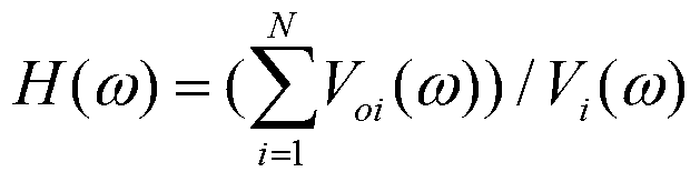
[0085] (2) For the input white noise signal V i And the vibration signal V of each measuring point oi Perform Fourier transform to obtain the vibration frequency response curve H(ω) of the transformer winding:

[0086] H ( ω ...


PUM


Abstract

The invention discloses a method for identifying modal parameters of a transformer coil. The method includes the following steps: vibration signals of all measure points of the transformer coil are collected; Fourier transformation is carried out on the vibration signals, and a vibration frequency response curve of the transformer coil is obtained; Fourier inversion is carried out, and free vibration signals of the transformer coil are obtained; wavelet conversion is carried out on the free vibration signals through Morlet wavelets, and a wavelet transformation time-frequency diagram is made; wavelet ridges are extracted from the wavelet transformation time-frequency diagram, and the vertical coordinate of each wavelet ridge is inherent frequency of each step of the transformer coil; the damping ratio of inherent frequency of all the steps is calculated; a coil vibration mode of the inherent frequency of each step is calculated. With the method, the mode parameters of the transformer coil can be accurately and efficiently identified. Design, manufacturing, coil deformation detection and state evaluation are convenient to carry out on a coil structure.

Description

technical field [0001] The invention relates to the technical field of transformer parameter identification, in particular to a transformer winding modal parameter identification method. Background technique [0002] The transformer is one of the most important equipment in the power system, and its operation stability has a great influence on the safety of the power system. At present, the operating environment of substation equipment and lines is not optimistic. The deformation caused by the impact of external short circuit on transformer winding is a relatively common fault in the process of transformer operation, which poses a great threat to the safe operation of the system. [0003] After the transformer suffers a sudden short circuit, the huge short-circuit electromotive force makes the winding vibration intensify, so that the winding may be loosened or deformed first. A large number of experimental studies have shown that transformer winding deformation has a cumula...

Claims


Application Information

Patent Timeline
Patent Type & Authority Applications(China)
IPC IPC(8): G01R31/00G01R23/02G01R23/16G01R27/02
Inventor 王丰华耿超桂顺生
Owner SHANGHAI JIAO TONG UNIV
Why Eureka
Try Eureka