Die assembling, die locking and die disassembling method of metal die casting machine in metal special forming technology and mechanism thereof

A mold clamping and mold splitting technology, which is applied in the field of metal die casting machine mold clamping, mold clamping and mold separation and its mechanism in the metal special forming technology, can solve the problems of no quantification, insufficient mold clamping, difficulty in manufacturing and installation, etc. Achieve the effects of simple control and operation, ensuring safety without overloading, and convenient design and manufacture

Inactive Publication Date: 2012-04-25
SUZHOU SANJI FOUNDRY EQUIP
View PDF5 Cites 7 Cited by
  • Summary
  • Abstract
  • Description
  • Claims
  • Application Information

AI Technical Summary

Problems solved by technology

[0004] From the working principle of the clamping mechanism described above, it can be seen that the use of the toggle mechanism as the clamping and clamping mechanism has the following disadvantages: 1) The dead point of the movable template is determined by the distance between the fixed template and the rear plate of the die-casting machine position, when the thickness of various modules is different, there must be a set of adjustment mechanism to precisely adjust the distance between the fixed template and the rear plate of the die-casting machine
When the distance is too large, the mold clamping will not be in place; if the distance is too small, the clamping force after mold clamping will exceed the value and cause component damage, such as tie rod breakage
2) Theoretically speaking, when the toggle mechanism is at the dead point, the driving force of the piston can generate infinite clamping force, and there is no quantifiable relationship between the two forces, so it is impossible to judge whether the die-casting machine has reached the rated Clamping force
If there is a small negative deviation when adjusting the distance between the fixed template and the rear plate, the long connecting rod will force the movable template to lock, and excessive clamping force will be generated by forcing the component to deform, resulting in damage to the component
3) The structure of the toggle mechanism and the auxiliary crosshead guide mechanism is complicated, and it is difficult to manufacture and install

Method used


Image

  • Die assembling, die locking and die disassembling method of metal die casting machine in metal special forming technology and mechanism thereof
  • Die assembling, die locking and die disassembling method of metal die casting machine in metal special forming technology and mechanism thereof

Examples


Embodiment Construction

[0009] specific implementation plan

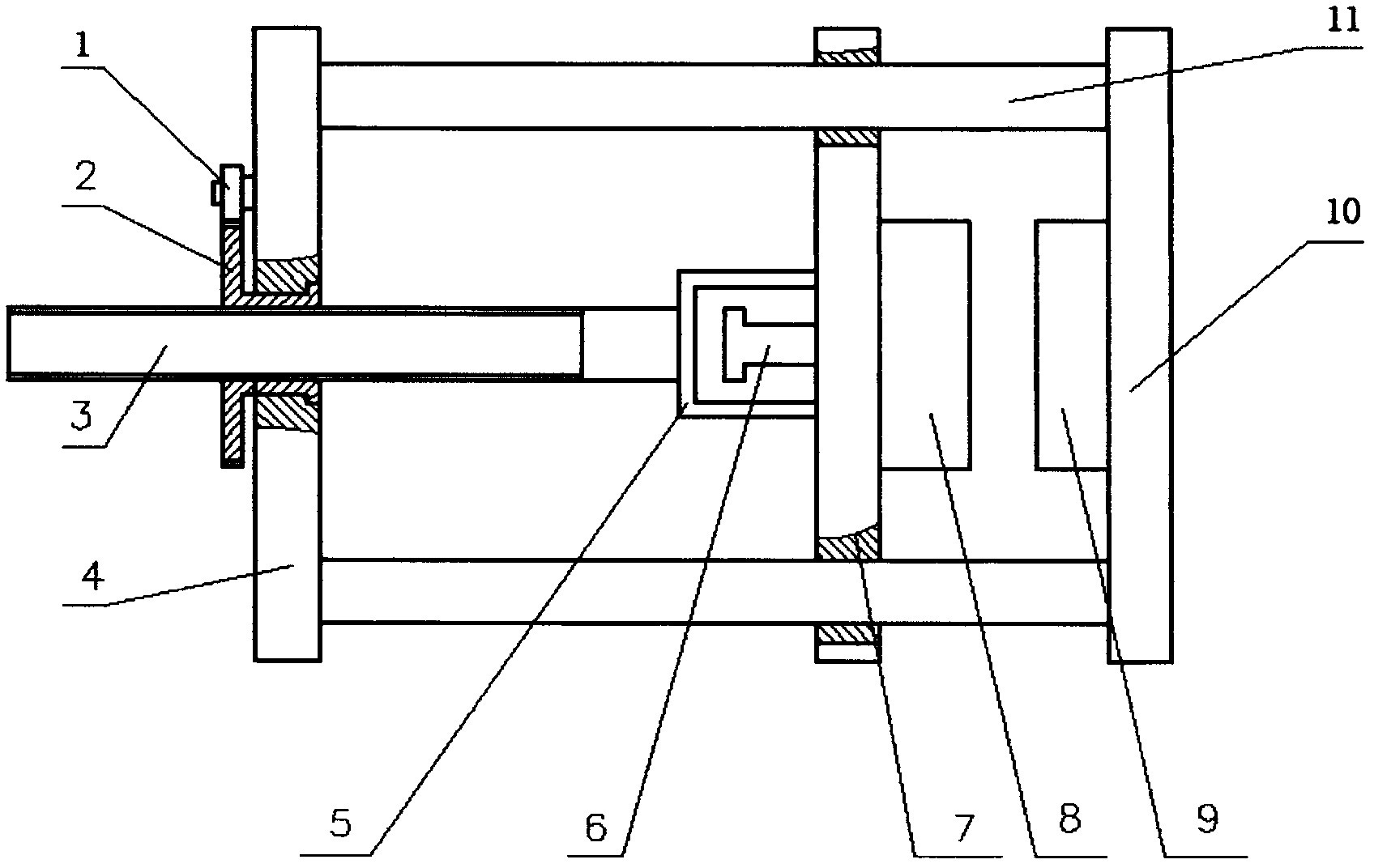
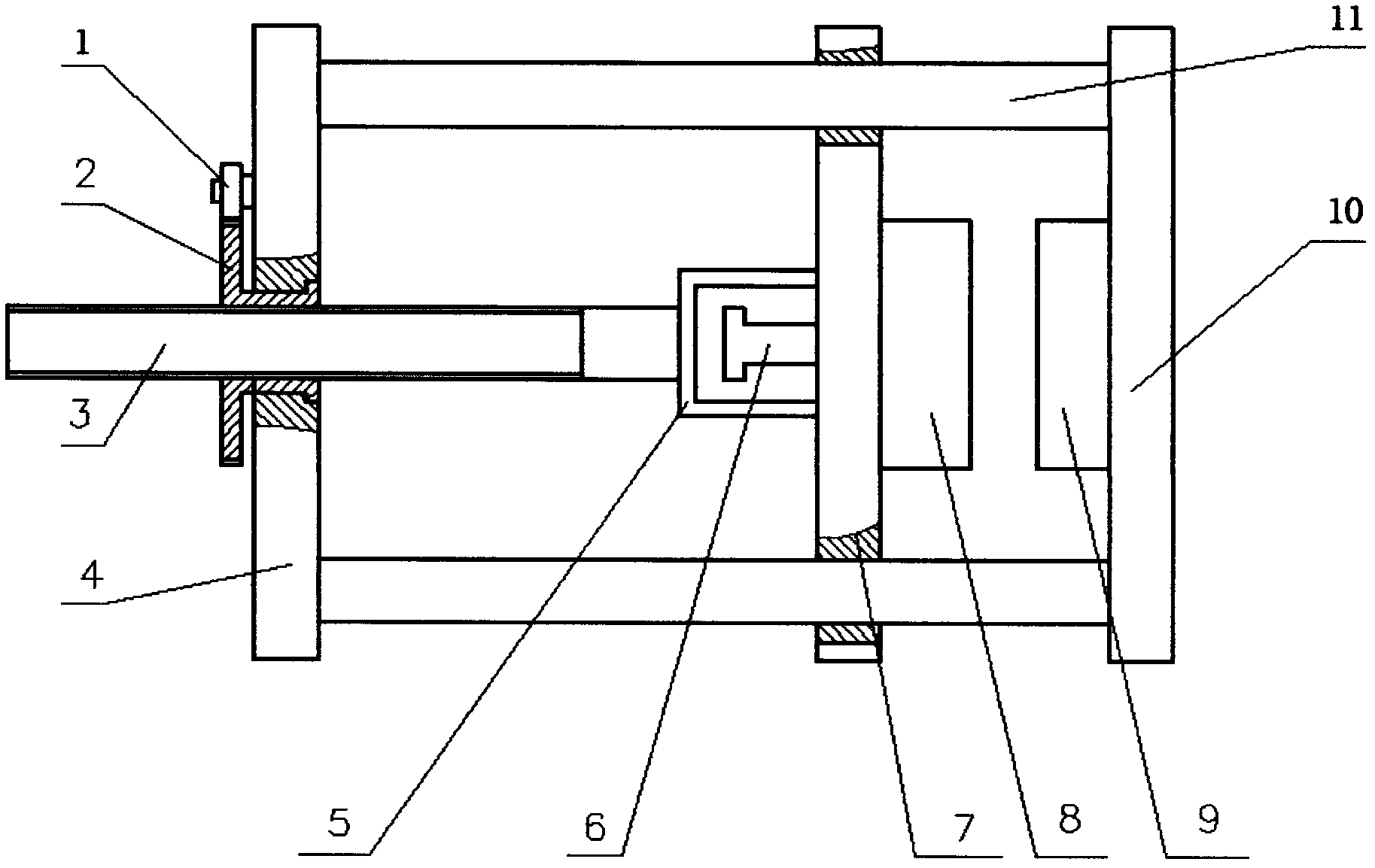
[0010] Four symmetrically distributed tie rods 11 are arranged between the rear plate 4 and the fixed plate 9 of the die-casting machine to form a frame. The movable template 7 is empty and can move on the pull rod 11. In 1 or 2 holes of the rear plate 4, a gear nut 2 that can be idling is set, and a thrust screw 3 is arranged in the gear nut 2, and the other end of the thrust screw 3 is consolidated with the supporting frame 5 above the movable template 7. A two-speed hydraulic motor 1 is arranged on the outer side of the rear plate 4 . The hydraulic motor 1 drives the gear nut 2 to rotate through the gear. The gear nut 2 that can only rotate and cannot move quickly drives the thrust screw 3 and the movable template 7 to move close to the fixed template 9 to realize the mold clamping of the movable module 8 and the fixed module 10, and then change to a low-speed drive until the movable template 7 is inside the movable module 8 It is lo...


PUM


Abstract

Die assembling, die locking and die disassembling actions of a die casting machine are basic functions for producing qualified casts. The conventional die casting machine adopts a hydraulic oil cylinder for pushing a toggle rod mechanism for performing the die assembling, die locking and die disassembling actions, the die locking force is difficult to regulate, and the toggle rod mechanism and an auxiliary crosshead guide mechanism are complex and bulky in structures and difficult to manufacture and mount. The invention provides a spiral type die assembling, die locking and die disassembling mechanism, and a hydraulic motor is adopted for driving a gear nut, thereby rotating a thrust screw rod for generating mobile feed motion and further pushing a movable die plate to realize fast die assembling and die locking; and the fast die disassembling can be realized when the hydraulic motor rotates in reverse direction. The mechanism can accurately figure out the die locking force. Simultaneously, an original regulating mechanism for regulating the distance between a rear plate and a fixed die plate is not required, the integral structure of the die casting machine is greatly simplified, and the control and the operation are simpler.

Description

technical field [0001] A metal die-casting machine mold-clamping mold-parting method in special metal forming technology and a mechanism for realizing the method. Background technique [0002] When the die-casting machine is working, the die-casting can only be realized after the fixed module in the fixed template and the movable module in the movable template are molded and locked. The high-pressure melt entering the mold cavity during die-casting will generate a huge force separating the fixed and movable plates. In order to ensure the quality of die casting, a huge clamping force should be provided in a short time of die casting forming. Due to the importance of the clamping force, the size of the clamping force becomes the basis for the classification of die casting machine specifications. [0003] The current technology is to arrange a toggle mechanism composed of six components symmetrically on the left and right in the middle of the die-casting machine. A high-pres...

Claims


Application Information

Patent Timeline
Patent Type & Authority Applications(China)
IPC IPC(8): B22D17/26
Inventor 许善新陈余秋沈世德贾祥磊
Owner SUZHOU SANJI FOUNDRY EQUIP
Why Eureka
Try Eureka