Liquid Discharging Apparatus and Control Method Therefor

a technology of liquid discharge nozzle and control method, which is applied in the direction of printing and other printing apparatus, can solve the problems of ink to remain in the ink discharge outlet, ink to be damaged, and difficult to properly discharge ink, so as to reduce enhance the cleaning effect of the liquid discharge nozzle and the adjacent areas. , the effect of reducing the time required for a series of performance maintaining operations

Inactive Publication Date: 2008-02-28
SONY CORP
View PDF6 Cites 30 Cited by
  • Summary
  • Abstract
  • Description
  • Claims
  • Application Information

AI Technical Summary

Benefits of technology

[0008]According to the liquid discharging apparatus, the liquid discharge surface of the liquid discharge head is not damaged, cleaning effects in the liquid discharge nozzle and the adjacent areas are enhanced, and the time required for a series of performance maintaining operations is reduced. As a result, the time required for a series of operations from wiping the liquid discharge surface to preliminarily discharging, which function as the performance maintaining operations of the liquid discharge head, is reduced, thus reducing a total print time.

Problems solved by technology

This makes it difficult to properly discharge ink.
However, in the technique described in Japanese Unexamined Patent Application Publication No. 57-034969, since blades formed of a relatively hard rubber or the like are pressed against an ink discharge surface of a print head and slid over the ink discharge surface to wipe off ink deposited on the ink discharge surface, the ink discharge surface may be damaged by being subjected to a strong force applied by the blades.
Additionally, the technique using the blades described above depends solely on wiping effects, but only performing wiping may cause ink to remain in ink discharge outlets.
If a plurality of blades are used in order to wipe a line print head, in which a large number of ink discharge nozzles are arranged so as to correspond to the full width in a print area, problems arise in which an ink discharge surface may be damaged and ink may remain in ink discharge outlets and the adjacent areas, as in the above case.
Since the capacity of the cap member to hold ink is limited, this technique has a problem in which the cap member must be handled as a consumable item and replaced with a new one multiple times. Furthermore, since an area (range) for preliminarily discharging ink to the cap member is limited, the cap member must be moved several times for performing necessary preliminary discharge, and therefore, a problem arises in which an actual print time period is increased.
Additionally, when continuous printing is performed, since an operation of moving the cap member and other operation are included, a problem arises in which the actual print time period is increased correspondingly.

Method used


Image

  • Liquid Discharging Apparatus and Control Method Therefor
  • Liquid Discharging Apparatus and Control Method Therefor
  • Liquid Discharging Apparatus and Control Method Therefor

Examples


Embodiment Construction

[0024]Embodiments of the present invention are described below with reference to the drawings.

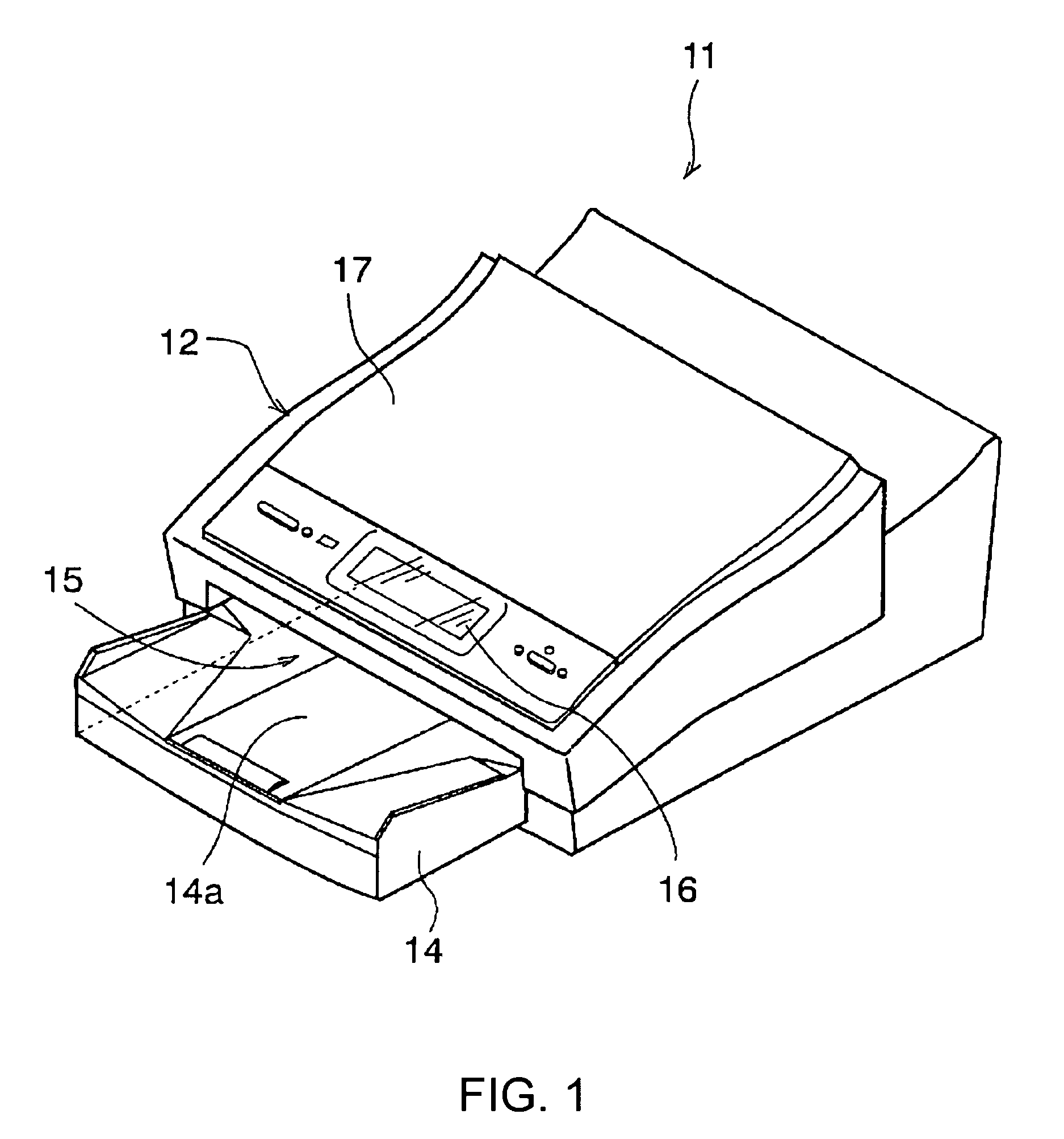
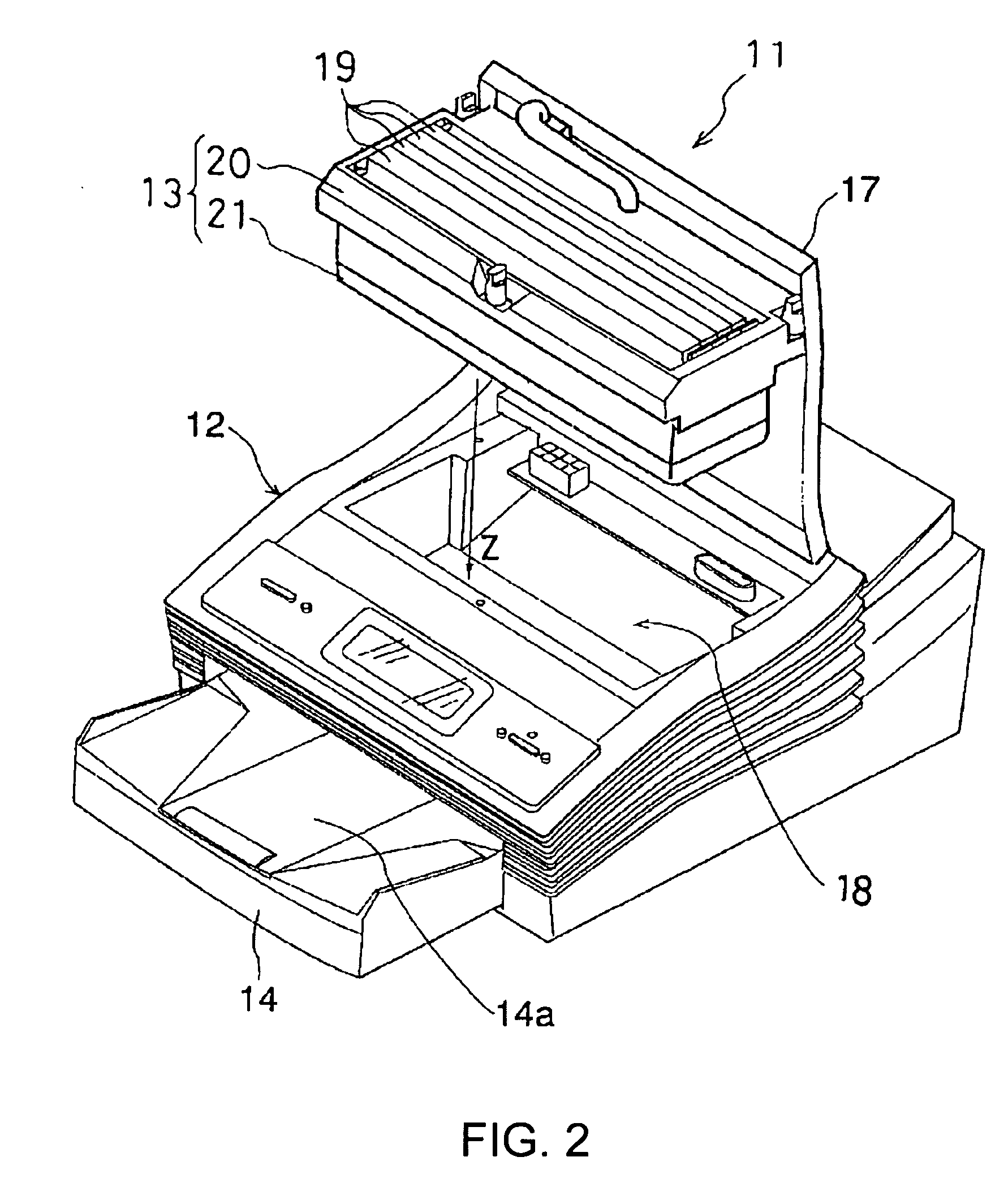
[0025]FIG. 1 is a perspective view of an embodiment of an inkjet printer as an example of a liquid discharging apparatus according to the present invention. This inkjet printer 11 is configured to form an image by discharging ink droplets to a predetermined point of a sheet of recording paper and includes a printer body 12, a head cartridge 13 (see FIG. 2), and a recording-paper tray 14.

[0026]The printer body 12 accommodates therein a conveyance mechanism for conveying recording paper held in the recording-paper tray 14 and an electric circuit for performing proper print on the recording paper, which serves as an object to be discharged. The recording-paper tray 14 is removably fit in a tray insertion slot 15 disposed at a lower front portion of the printer body 12. The tray insertion slot 15 also functions as a paper output slot. A sheet of recording paper that has been printed inside the ...


PUM


Abstract

In a liquid discharging apparatus for discharging droplets from a liquid discharge nozzle to a discharge object to be discharged and in a method for controlling the liquid discharging apparatus, cleaning effects for the ink discharge nozzle and the adjacent areas can be enhanced, and the time required for a series of performance maintaining operations can be reduced. The apparatus includes a platen plate for supporting recording paper as the discharge object, defining a positional relationship between the discharge object and the liquid discharge head, and receiving the droplets discharged from the liquid discharge head. Ink droplets are preliminarily discharged from the ink discharge nozzle to the platen plate.

Description

TECHNICAL FIELD[0001]The present invention relates to a liquid discharging apparatus for discharging droplets from a liquid discharge nozzle of a liquid discharge head to an object to be discharged and relates to a control method therefor.BACKGROUND ART[0002]Inkjet image forming apparatuses, for example, inkjet printers, have become widely available because of their low running costs, ease of colorization of a print image and miniaturization, and the like. Inkjet printers record an image by discharging small amounts of ink from tiny ink discharge outlets extending through an ink discharge surface of a print head. If print operation has not been performed for a long period of time and thus ink has not been discharged from the ink discharge outlets of the print head for such a long period, ink deposited on the ink discharge outlets formed through the ink discharge surface and the adjacent areas in the previous print operation may have been vaporized, dried, solidified, and hardened. T...

Claims


Application Information

Patent Timeline
Patent Type & Authority Applications(United States)
IPC IPC(8): B41J29/38B41J2/04B41J2/165
CPCB41J2/16526B41J11/06B41J2/16585B41J2/16535B41J2/07B41J2/175B41J29/393
Inventor YAKURA, YUJISUZUKI, KENJITAKAHASHI, TAKANORI
Owner SONY CORP
Why Eureka
Try Eureka