
Blowing structure for unloading device of vertical centrifuge

A vertical centrifuge and unloading device technology, applied in the field of centrifuges, can solve the problems of inability to remove, damage to the scraper shaft and scraper plate, blockage of the filter screen, etc., and achieve the effect of improving the cleaning effect and improving the mechanical strength.

Active Publication Date: 2011-09-14
ANHUI PUYUAN SEPARATION MACHINERY MFG CO LTD
View PDF5 Cites 4 Cited by
  • Summary
  • Abstract
  • Description
  • Claims
  • Application Information

AI Technical Summary

Problems solved by technology

[0010] 1. Due to the gap of 3-5 mm between the scraper and the filter screen, and due to the viscosity of the material, there will always be a layer of 3-5 mm thick on the filter after each discharge by the scraper board. Material residue (commonly known as filter cake) cannot be removed, which leads to blockage of the filter screen and reduces the solid-liquid separation effect of the vertical centrifuge;
[0011] 2. Because the material generally has a certain viscosity, it is difficult to form broken particles. In this way, the material scraped by the scraper is easy to accumulate around the discharge hole. After a long working time, the discharge hole is blocked and becomes smaller, and finally blocked The discharge hole makes the discharge unsmooth. When the scraper moves to the material accumulated at the bottom of the drum, the scraper stirs in the material, which may easily cause damage to the scraper shaft and the scraper.
[0012] At present, in order to remove the material residue remaining on the filter screen, water washing is usually used, but this will cause material waste

Method used


Image

  • Blowing structure for unloading device of vertical centrifuge
  • Blowing structure for unloading device of vertical centrifuge
  • Blowing structure for unloading device of vertical centrifuge

Examples


Embodiment Construction

[0036] Embodiments of the present invention will be specifically described below in conjunction with the accompanying drawings:

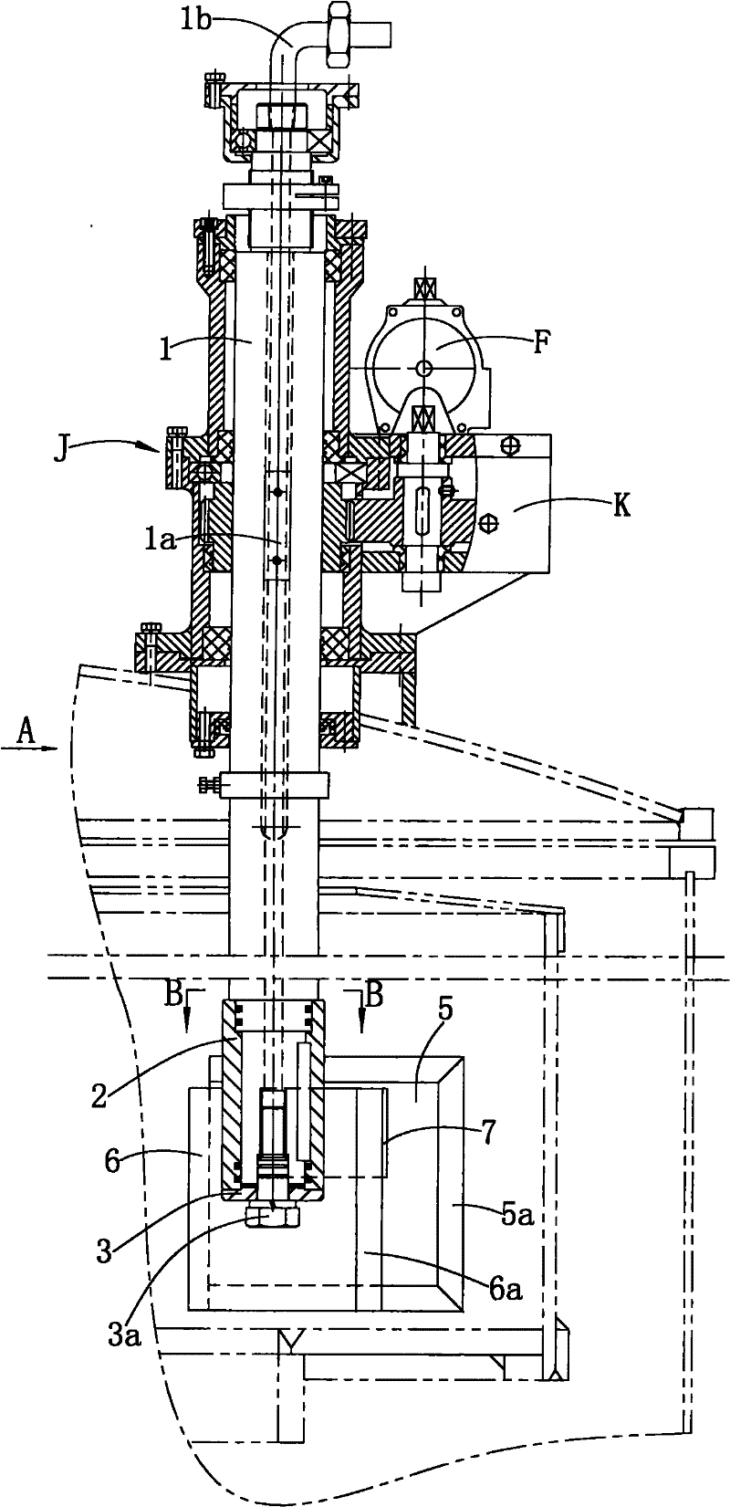
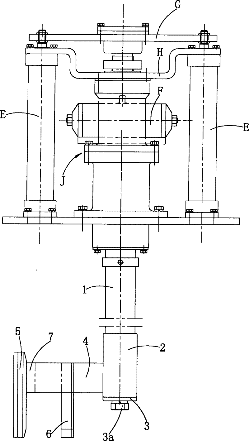
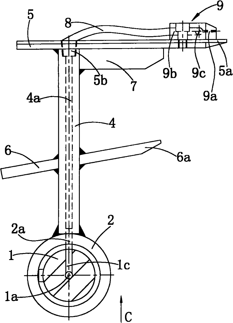
[0037] see Figure 1-Figure 7 : This air blowing structure comprises vertical scraper shaft 1, the scraper assembly that is connected at the lower end of scraper shaft 1.

[0038] There is a first air channel inside the scraper shaft 1, the first air channel is composed of an axial vertical hole 1a and a radial horizontal hole 1c, the vertical hole 1a runs through the scraper shaft 1 from top to bottom, and the upper end of the vertical hole 1a is the first air channel The air inlet is installed with an air nozzle 1b, the lower end of the vertical hole 1a is shaped on an internal thread, the horizontal hole 1c is located on the lower side of the scraper shaft 1 and communicates with the vertical hole 1a, and the horizontal hole 1c is the air outlet of the first air channel.

[0039] The scraper assembly includes a shaft sleeve 2, an end cover 3, a ...


PUM


Abstract

The invention relates to a blowing structure for an unloading device of a vertical centrifuge, and the blowing structure comprises a vertical scraper shaft and a scraper assembly connected to the lower end of the vertical scraper shaft, wherein the scraper assembly comprises a scrapping plate; a first air channel is arranged in the vertical scraper shaft; the scraper assembly is provided with a second air channel; the lower side of the first air channel is in sealing communication with the air inlet of the second air channel; and the air outlet of the second air channel is close to the working end of the scrapping plate. The first and second air channels which are in sealing communication are arranged and the air outlet of the second air channel is close to the working end of the scrapping plate, so when the unloading device is used for unloading the materials attached on a filter screen, the scrapping plate slowly cuts the materials from up to down along the rotation direction of a rotary drum, and meanwhile, the compressed air blows the material residues reserved on the filter screen through the air outlet of the second air channel, and the then material residues can vibrate under the action of the blown air and completely drop off from the filter screen, thereby achieving the purposes of recovering the materials and dredging the filter screen. The blowing structure has the advantages of removing the material residues reserved on the filter screen and dredging the filter screen.

Description

technical field [0001] The invention relates to the technical field of centrifuges, in particular to an air blowing structure used in a discharge device of a vertical centrifuge to remove material residues on the filter screen of the vertical centrifuge. Background technique [0002] Centrifuges are widely used and are mainly used to separate and dry liquids in materials. [0003] The structure of the existing vertical centrifuge is as follows: the base is provided with a casing, the casing is equipped with a drum, the bottom of the drum has a discharge hole, the top of the casing is provided with a cover, and the cover is provided with a feeding device. And the unloading device, there are several through holes on the side wall of the drum, the inner wall of the drum is provided with a filter screen, and the drum is driven by the driving device. [0004] The unloading device includes a vertical scraper shaft, a scraper assembly, two vertical cylinders, a pneumatic actuator,...

Claims


Application Information

Patent Timeline
Patent Type & Authority Applications(China)
IPC IPC(8): B04B15/06
Inventor 唐海贝
Owner ANHUI PUYUAN SEPARATION MACHINERY MFG CO LTD
Learn More