Material strip deflection correction control device and method

A control device and tape technology, applied in thin material handling, transportation and packaging, winding strips, etc., can solve the problems of tape winding deviation, tape damage, uneven pressure, etc.

Inactive Publication Date: 2011-09-14
唐虎
View PDF3 Cites 3 Cited by
  • Summary
  • Abstract
  • Description
  • Claims
  • Application Information

AI Technical Summary

Problems solved by technology

The general driven roller will run along with the material belt when it receives the winding force of the material belt, but the pressure of the roller itself will be uneven, so after the material belt is transported for a certain period of time, it will be on the roller. Deflection o

Method used


Image

  • Material strip deflection correction control device and method
  • Material strip deflection correction control device and method

Examples


Embodiment Construction

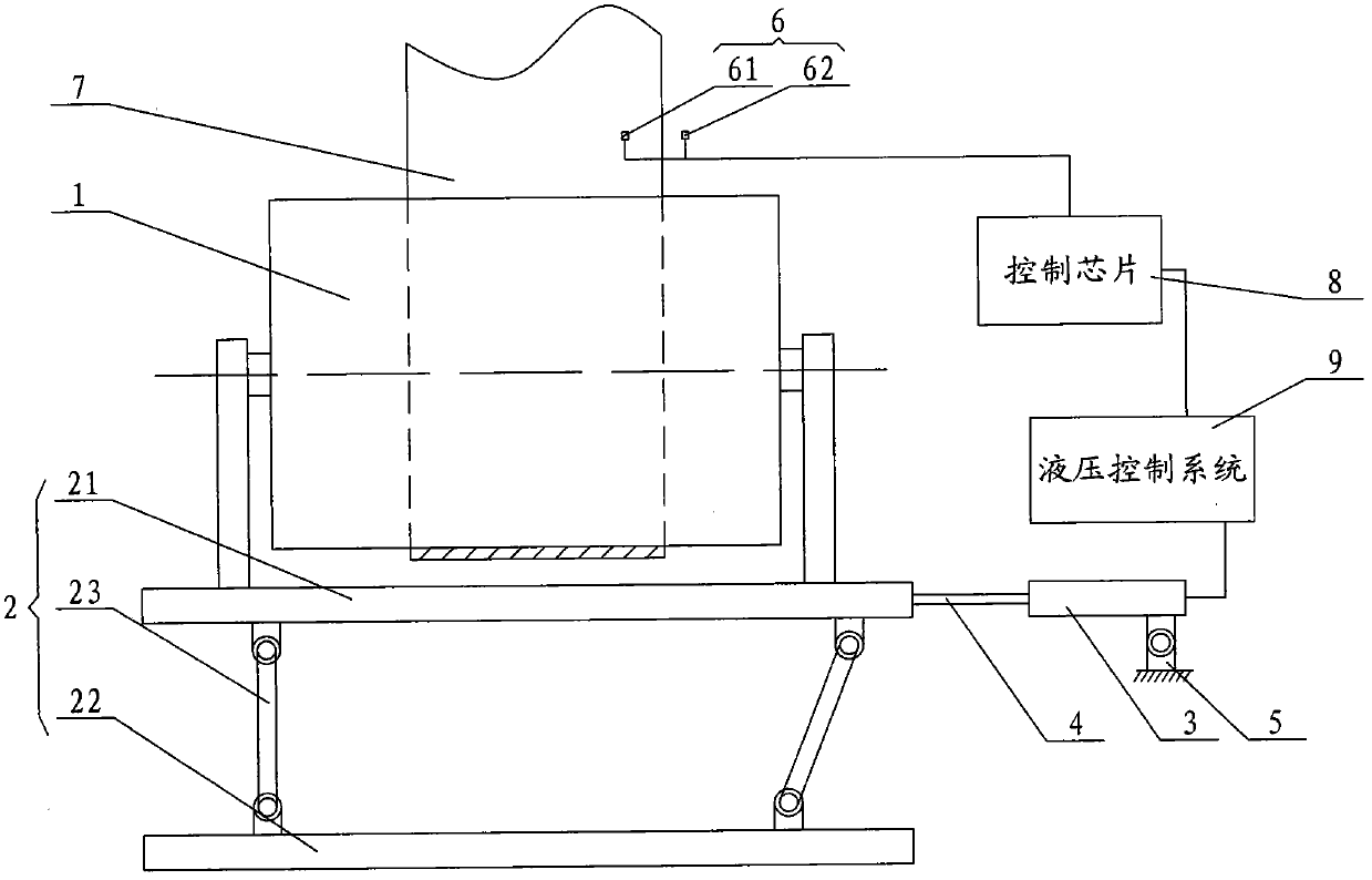
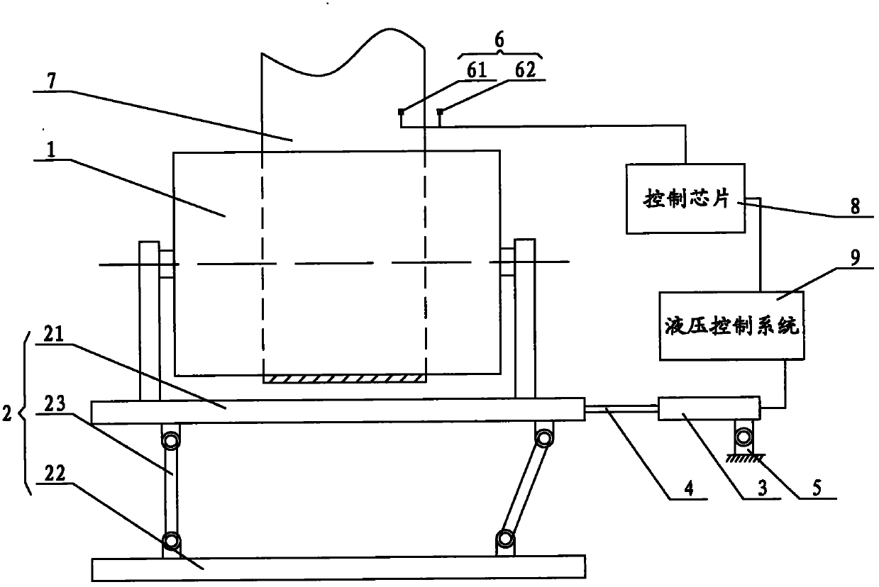
[0017] Such as figure 1 As shown, the material belt deviation correction control device according to the present invention mainly includes a roller 1, a roller inclination control mechanism 2, a driving cylinder 3 and two optical sensors 6 installed on one side of the material belt. 1 is installed on the roller inclination control mechanism 2, one end of the roller inclination control mechanism 2 is connected with the piston rod 4 of the drive cylinder 3, and the two optical sensors 6 are respectively located on the outside of one side of the material belt 7 And on the inner side, two light sensors 6 are electrically connected to the control chip 8 , and the driving cylinder 3 is connected to the hydraulic control system 9 , and the hydraulic control system 9 is electrically connected to the control chip 8 .

[0018] Further, the roller inclination control mechanism 2 includes an upper panel 21 and a lower bottom plate 22, and the upper panel 21 and the lower bottom plate 22 a...


PUM


Abstract

The invention provides a material strip deflection correction control device which mainly comprises a roller, a roller slope control mechanism, a driving cylinder and two photosensors mounted on one side edge of a material strip. The material strip deflection correction control device is characterized in that the roller is mounted on the roller slope control mechanism; one end of the roller slope control mechanism is connected with the piston rod of the driving cylinder; the two photosensors are respectively located on the outer side and inner side of one side edge of the material strip, and are electrically connected to a control chip; the driving cylinder is connected with a hydraulic control system; and the hydraulic control system is electrically connected with the control chip. Through the roller slope control device, an upper panel can be driven by the piston rod of the driving cylinder to move left and right, and the upper panel can be driven by two hinged support plates to generate deflection in the horizontal direction during the movement of the upper panel so as to control the force of the material strip on the roller and finally adjust the position of the material strip on the roller. The invention also discloses a material strip deflection correction control method.

Description

technical field [0001] The invention relates to a device and method for controlling the inclination of rollers, which are applied to various industries involving material belt transmission. Background technique [0002] At present, many kinds of material belts are arranged in rolls. During the process of opening or winding the material belts, rollers are needed for transmission. The material belts are erected on the rollers, and the material belts are driven forward by the axles of the rollers, or the material belts In the process of advancing, the rollers are driven to run. Therefore, in the process of use, the rollers are divided into driving rollers and driven rollers. The general driven roller will run along with the material belt when it receives the winding force of the material belt, but the pressure of the roller itself will be uneven, so after the material belt is transported for a certain period of time, it will be on the roller. Deflection occurs, and if the def...

Claims


Application Information

Patent Timeline
IPC IPC(8): B65H23/26
Inventor 唐虎
Owner 唐虎
Why Eureka
Try Eureka