Lifting mechanism for glass conveying roller way

A technology for conveying rollers and glass, applied in the directions of conveyor objects, transportation and packaging, furnaces, etc., can solve the problem that the movement synchronization of the two drive shafts cannot be completely guaranteed, and achieves simple structure, convenient production, and solves the problem of deflection. Effect

Inactive Publication Date: 2017-03-22
BENGBU TRIUMPH ENG TECH CO LTD
View PDF5 Cites 0 Cited by
  • Summary
  • Abstract
  • Description
  • Claims
  • Application Information

AI Technical Summary

Problems solved by technology

Since the crank and drive shaft are also connected by a key, there is the same problem as problem 1
Although the connecting rod has a certain adjustment function, it cannot completely guarantee the synchronization of the movement of the two transmission shafts.

Method used


Image

  • Lifting mechanism for glass conveying roller way

Examples


Embodiment Construction

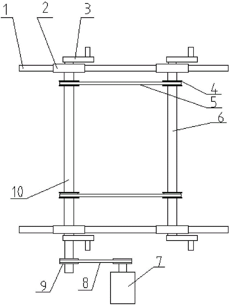
[0012] Referring to the drawings, a lifting mechanism for a glass conveying roller table includes a lifting mechanism base frame 1 and a motor 7. The lifting mechanism base frame 1 includes a front lifting mechanism base and a rear lifting mechanism base; a front lifting mechanism base and a rear lifting mechanism base A left drive shaft 10 and a right drive shaft 6 are installed between them through the bearing seat 2. The left drive shaft 10 and the right drive shaft 6 are respectively cranked at both ends, and the outer end of the left drive shaft 10 is connected to the motor through the drive sprocket 9 and the drive chain 8. 7. The left transmission shaft 10 and the right transmission shaft 6 are connected by a transmission sprocket 4 and a transmission chain 5. The left transmission shaft 10 and the front of the right transmission shaft 6 are connected by a front transmission sprocket and a front transmission chain, and the left transmission shaft 10 and the rear of the ri...


PUM


Abstract

The invention discloses a lifting mechanism for a glass conveying roller way. The lifting mechanism comprises a lifting mechanism base framework and a motor, wherein the lifting mechanism base framework comprises a front lifting mechanism base and a rear lifting mechanism base; a left transmission shaft and a right transmissions haft are mounted between the front lifting mechanism base and the rear lifting mechanism base through a bearing base; the two ends of the right transmission shaft are separately equipped with cranks; the outer end of the left transmission shaft is connected with the motor through a drive chain wheel and a drive chain; and the left transmission shaft is connected with the right transmission shaft through a transmission chain wheel and a transmission chain. The lifting mechanism disclosed by the invention is simple in structure, and is convenient to manufacture, mount and debug, and solves the declining problem, in a lifting process, of glass plates.

Description

Technical field [0001] The invention relates to the field of glass production lines, in particular to a lifting mechanism for glass conveying rollers. Background technique [0002] At the cold end of the glass production line, it is sometimes necessary to sample the original glass plate, which requires the glass conveying roller to have the function of lifting the glass plate at a certain position. Usually a lifting mechanism is added to a certain section of roller table to achieve this purpose. The old-style lifting mechanism often has the phenomenon of deflection of the glass plate during the lifting process. [0003] The structure of the old lifting mechanism is similar to that of the new lifting mechanism, but there are the following problems: 1. The crank and the drive shaft are connected by a key. It can be seen from the figure that there is a crank at each end of a rotating shaft. In order to realize the synchronization of the lifting process, the starting position and swi...

Claims


Application Information

Patent Timeline
Patent Type & Authority Applications(China)
IPC IPC(8): B65G49/06B65G47/34
CPCB65G47/34B65G49/063
Inventor 纪圣杰葛军蒋涛涛谭玉良何思源徐星王松张德三詹滕张丽
Owner BENGBU TRIUMPH ENG TECH CO LTD
Why Eureka
Try Eureka