Cyclone sand washing device

A sand washing device and sand washing technology, which is applied in the direction of flushing wellbore, wellbore/well parts, earthwork drilling and production, etc. It can solve the problems of low efficiency of sand washing tools and difficult removal of sand settling, and achieve the effect of improving efficiency

Inactive Publication Date: 2011-09-14
CHINA NAT PETROLEUM CORP CHUANQING DRILLING ENG CO LTD CHANGQING DOWNHOLE TECH CO
View PDF7 Cites 4 Cited by
  • Summary
  • Abstract
  • Description
  • Claims
  • Application Information

AI Technical Summary

Problems solved by technology

[0002] In recent years, with the increasing development of oil and gas fields, the proportion of horizontal wells is increasing, while the development of corresponding horizontal downhole tools is relatively lagging behind. The existing sand washing tools are inefficient in horizontal oil and gas sand washing operations. The grit at the bottom of the pipe is difficult to remove

Method used


Image

  • Cyclone sand washing device
  • Cyclone sand washing device
  • Cyclone sand washing device

Examples


Embodiment 1

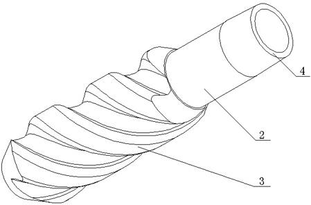
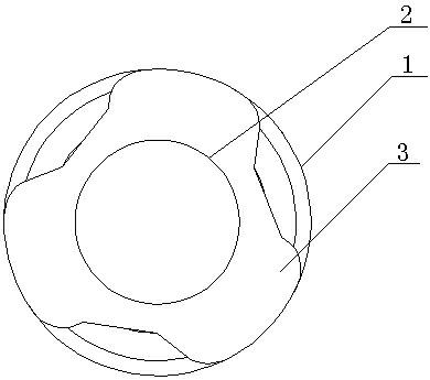
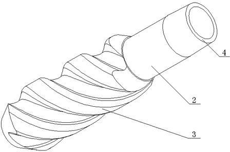
[0016] Such as figure 1 , figure 2 As shown in the structural schematic diagram of this cyclone sand washer, the body 2 of the sand washer is placed at the bottom of the casing 1. There is a spiral groove 3 on the outside of the body 2 of the sand washer, and there is a connector on the upper end of the body 2 of the sand washer 4.

[0017] The sand washer body 2 is placed at the position of the horizontal sand settling section of the inner bottom of the casing 1 or the position of the vertical well section of the casing 1 within 0.5 m from the sand surface.

[0018] The outer diameter of the spiral groove 3 is slightly smaller than the inner diameter of the casing 1, and the sand flusher body 2 is a hollow tubular structure with open ends.

Embodiment 2

[0020] The structure of the spiral groove 3 in this embodiment is a trapezoidal three-thread thread, the spiral lead is between 300 mm and 400 mm, and the crimping of the three-thread spiral is transitioned from the helix surface fillet.

[0021] When performing reverse circulation killing operations, the sand washer body 2 is threadedly connected with a conveying pipe through the upper connector 4, and the sand washer body 2 is conveyed and fixed to the bottom of the casing 1 through the conveying pipe. At this time, the fluid is in 2 Under the pressure of -3MPa, the flow enters the casing 1 at a flow rate of 200-300L / min. When the fluid flows through the body 2 of the sand flusher, a high-speed rotating water flow is formed under the action of the spiral groove 3. The rotating water flow can transfer the casing 1 The sedimented sand at the bottom is washed to the low end opening of the sand washer body 2, and finally discharged from the hollow cavity of the sand washer body 2 th...


PUM


Abstract

The invention relates to the field of oil-gas field mining machines, in particular to a cyclone sand washing device used in sand washing operation of a horizontal well of an oil-gas field. The cyclone sand washing device is characterized in that a sand washing device body is arranged at the bottom in a sleeve, and a spiral groove is arranged outside the sand washing device body; the sand washing device body is placed in the position of a horizontal sand settling section at the bottom in the sleeve or the position within 0.5m to the sand surface of a straight well section of the sleeve; a connecting head is arranged at the upper end of the sand washing device body; the sand washing device body is hollow, and open pipy structures are arranged at two ends of the sand washing device body; and the outer diameter of the spiral groove is smaller than the inner diameter of the sleeve. The invention provides the cyclone sand washing device which is high in sand washing efficiency and can thoroughly clear sand settled at the bottom of the sleeve.

Description

Technical field [0001] The invention relates to the field of oil and gas field mining machinery, in particular to a cyclone sand flusher used in sand flushing operations of horizontal wells in oil and gas fields. Background technique [0002] In recent years, as the development of oil and gas fields has increased, the proportion of horizontal wells has increased, and the development of corresponding horizontal downhole tools has been relatively lagging. The existing sand flushing tools are inefficient in the sand flushing operations of horizontal oil and gas, especially for casing. The sediment at the bottom of the tube is difficult to remove. Therefore, there is an urgent need to develop a simple and efficient sand flushing tool suitable for horizontal wells. Summary of the invention [0003] The purpose of the present invention is to provide a cyclone sand washing device with high sand washing efficiency and capable of completely removing sand settling at the bottom of the casi...

Claims


Application Information

Patent Timeline
Patent Type & Authority Applications(China)
IPC IPC(8): E21B21/00
Inventor 苏敏文韩虎成邓小强杜加玉
Owner CHINA NAT PETROLEUM CORP CHUANQING DRILLING ENG CO LTD CHANGQING DOWNHOLE TECH CO
Why Eureka
Try Eureka