Backlight module and fixing mechanism for same

A technology of backlight module and fixing mechanism, applied in the field of fixing mechanism, can solve the problems of easy failure of tape, high labor cost, poor accuracy, etc.

Inactive Publication Date: 2011-09-14
SHENZHEN CHINA STAR OPTOELECTRONICS TECH CO LTD
View PDF6 Cites 27 Cited by
  • Summary
  • Abstract
  • Description
  • Claims
  • Application Information

AI Technical Summary

Problems solved by technology

However, most tapes are prone to failure when tested in high-temperature and high-humidity

Method used


Image

  • Backlight module and fixing mechanism for same
  • Backlight module and fixing mechanism for same
  • Backlight module and fixing mechanism for same

Examples


Embodiment Construction

[0028] In order to make the above-mentioned purposes, features and advantages of the present invention more obvious and understandable, the preferred embodiments of the present invention will be specifically cited below, together with the accompanying drawings, for a detailed description as follows:

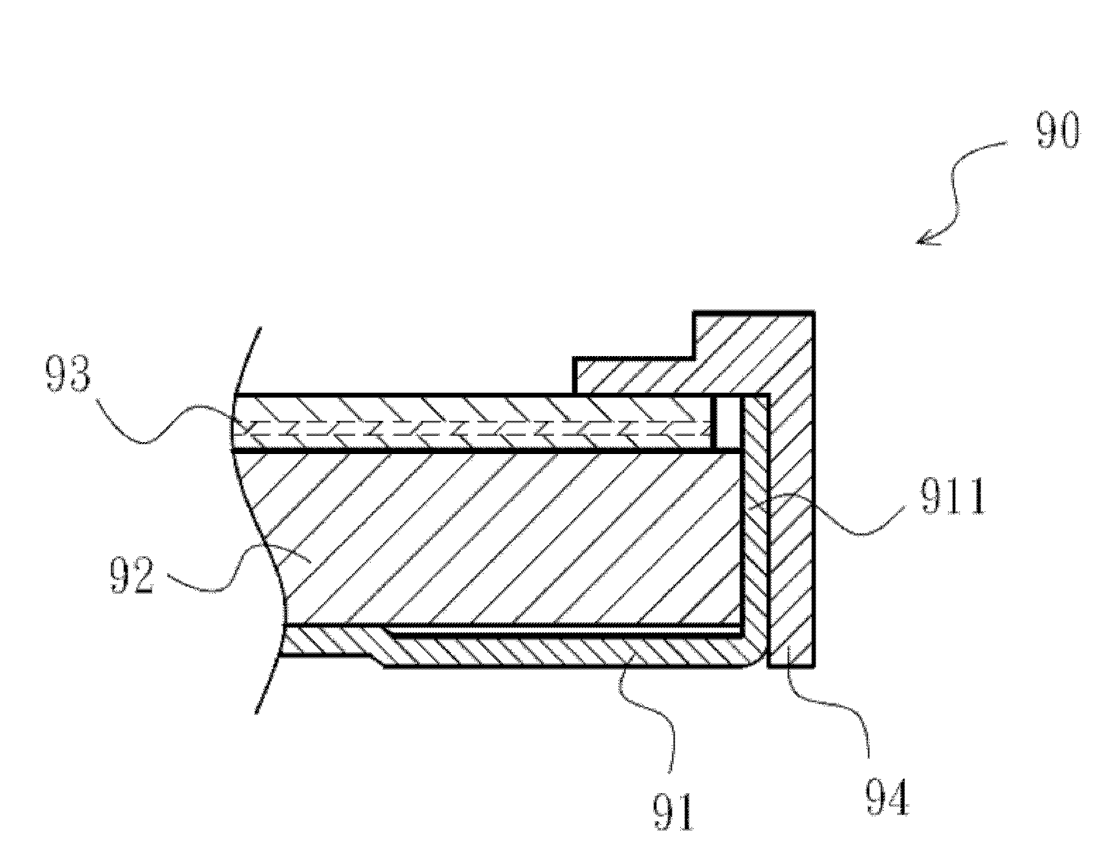
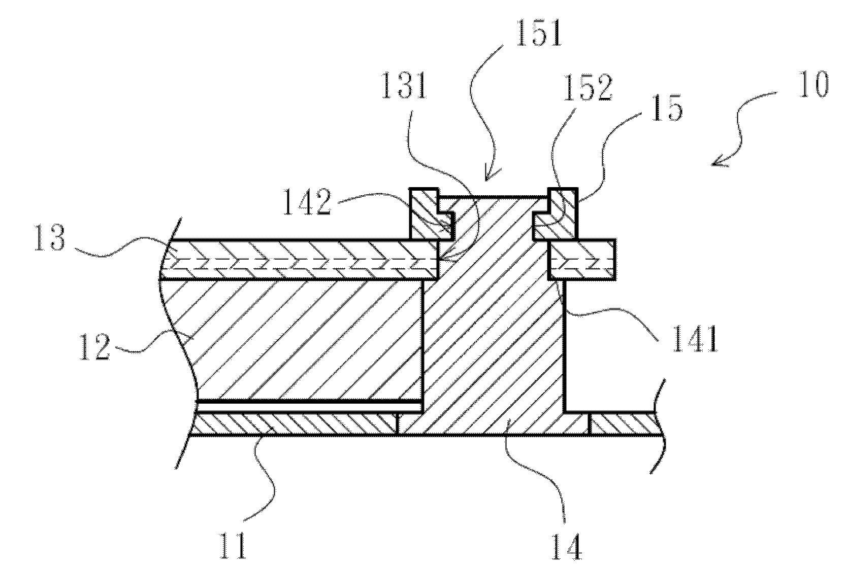
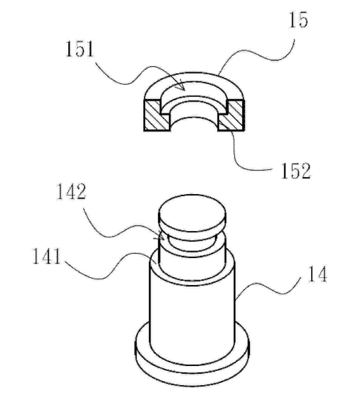
[0029] Please refer to figure 2 , figure 2 It is a partial sectional view of the first embodiment of the backlight module of the present invention. The backlight module 10 includes a back plate 11 , an optical component and a fixing mechanism for the optical component. In each embodiment of the present invention, the optical component is a light guide plate or a combination of a light guide plate and an optical film, and in this embodiment, the optical component includes a light guide plate 12 and an optical film 13 . The light guide plate 12 is arranged on the back plate 11, and the optical film 13 is arranged above the light guide plate 12. The optical film 13 may be a laye...


PUM


Abstract

The invention discloses a backlight module and a fixing mechanism for the same. The fixing mechanism comprises a plurality of fixing columns and a plurality of fixing pieces, wherein the plurality of fixing columns are convexly arranged on a back plate, and the fixing pieces are clamped to the upper ends of the fixing columns to fix an optical component. In addition, the fixing mechanism is made of an elastic material, so that the optical component can be fixed stably, a gap cannot be produced, and the positioning of the optical component cannot be released due to the influence of expansion caused by heat and contraction caused by cold.

Description

【Technical field】 [0001] The invention relates to a fixing mechanism for a backlight module, in particular to a fixing mechanism for fixing an optical component of the backlight module and the backlight module. 【Background technique】 [0002] Liquid crystal display panels (LCD panels) are now widely used in monitors, notebook computers, digital cameras and other electronic products with growth potential. After the LCD panel manufacturer produces the glass panel, it must first combine the color filter, the two are sealed and poured into the liquid crystal, and then combined with the backlight module, driver IC, control circuit board and other components to form an LCD module for sale to downstream manufacturers . [0003] The backlight module is one of the key components of the liquid crystal display. Since the liquid crystal itself does not emit light, the function of the backlight module is to supply sufficient brightness and evenly distributed light source so that it can ...

Claims


Application Information

Patent Timeline
IPC IPC(8): F21V17/10F21V13/00F21S8/00
CPCG02B6/0011G02F2201/46F21V17/10G02F1/1336F21S8/00F21V13/00G02B6/0088
Inventor 李全
Owner SHENZHEN CHINA STAR OPTOELECTRONICS TECH CO LTD
Why Eureka
Try Eureka