
Plastic formwork used for paving floor heating thermostat

A technology of plastic formwork and floor heating, which can be used in applications, household heating, household appliances, etc., and can solve problems such as unreasonable layout, long construction period, and heavy workload

Inactive Publication Date: 2013-03-20
顾世安
View PDF8 Cites 0 Cited by
  • Summary
  • Abstract
  • Description
  • Claims
  • Application Information

AI Technical Summary

Problems solved by technology

[0002] Due to the unreasonable layout of the pipe laying grooves on the existing formwork for floor heating laying, it is impossible to freely adjust the distance between the hoses for hot water supply, especially the hoses near the place where they come out of the manifold , because the hoses in this place are relatively dense, the direction of the hoses needs to be handled flexibly according to the conditions of the construction site. However, if the existing formwork is used, since there are no redundant pipe laying grooves on the formwork, the original formwork can only be destroyed. According to Due to the situation at the construction site, re-grooving made it very inconvenient to use the existing formwork for construction and installation. Not only the workload of the construction was heavy, but the construction period was also very long, which led to a substantial increase in construction costs

Method used


Image

  • Plastic formwork used for paving floor heating thermostat
  • Plastic formwork used for paving floor heating thermostat

Examples


Embodiment Construction

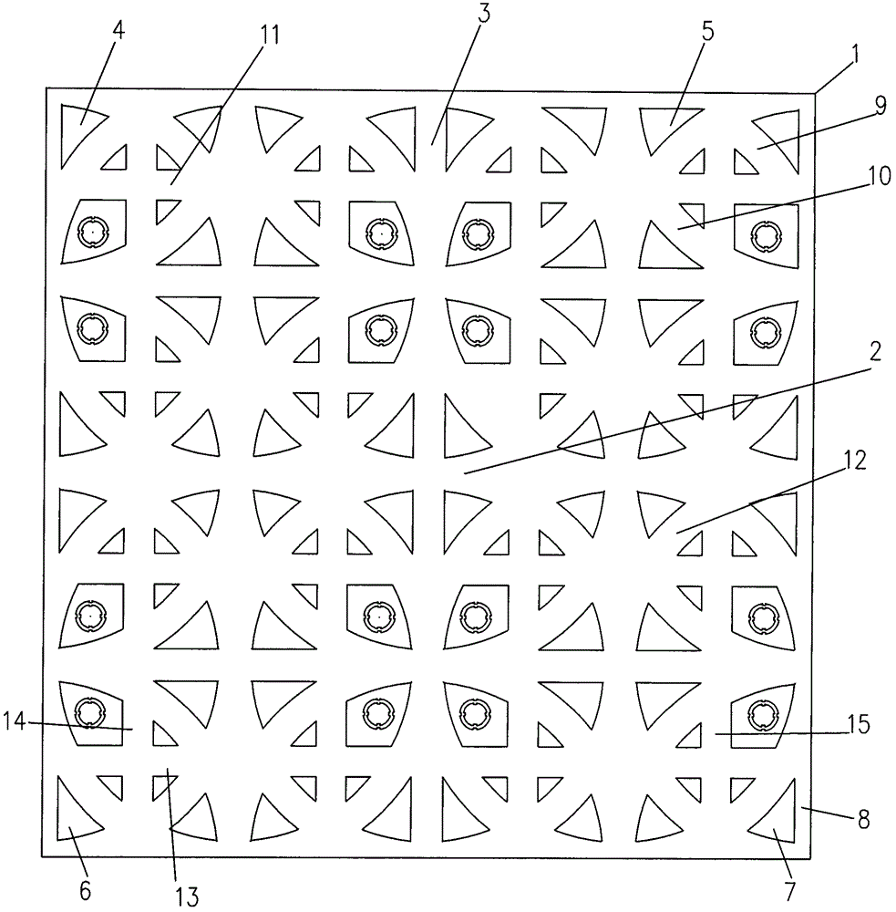
[0012] Such as figure 1 and figure 2 As shown, the plastic formwork for floor heating laying of the present invention includes a square plate body 1 made of plastic, the length of each side of the plate body 1 is 4R, and the upper surface of the plate body 1 is along the left and right sides of the plate body 1. The center line of the right side is provided with a pipe-laying groove 2, and the upper surface of the plate body 1 is provided with a B pipe-laying groove 3, A pipe-laying groove 2 and a B pipe-laying groove along the centerline of the front and rear sides of the plate body 1 3. Divide the upper surface of the plate body 1 into four equal-area square left front plates 4, right front plates 5, left rear plates 6 and right rear plates 7. The center of the plate 5, the left rear plate 6 and the right rear plate 7 is the center of the circle, and a circular C pipe-laying groove 9 with a central axis radius of R is provided. The central axis of each C pipe-laying groove...


PUM


Abstract

The invention relates to a plastic formwork used for paving a floor heating thermostat, which comprises a plate, wherein an A tube-paving slot is arranged on the upper surface of the plate along a neutral line of left and right sides of the plate; a B tube-paving slot is arranged on the upper surface of the plate along a neutral line of front and back sides of the plate; the upper surface of the plate is divided into four plate blocks which have same areas by the A tube-paving slot and the B tube-paving slot; the four plate blocks are respectively a left front plate block, a right front plate block, a left back plate block and a right back plate block; circular C tube-paving slots having a central axial radius R are arranged on the upper surface of the plate by respectively using the centers of the left front plate block, the right front plate block, the left back plate block and the right back plate block as the circle centers; and semicircular D tube-paving slots having the central axial radius R are arranged on the upper surface of the plate by respectively using the centers of left and right broadsides of the left front plate block, the right front plate block, the left back plate block and the right back plate block as the circle centers. The invention aims to provide the plastic formwork used for paving the floor heating thermostat, which can be used for reducing the construction period and can be more conveniently constructed and mounted. Besides, the plastic formwork has the advantages of long service life, capability of freely adjusting a distance between hoses, more uniform heat distribution and better heat supply effect.

Description

technical field [0001] The invention relates to a plastic template for floor heating laying. Background technique [0002] Due to the unreasonable layout of the pipe laying grooves on the existing formwork for floor heating laying, it is impossible to freely adjust the distance between the hoses for hot water supply, especially the hoses near the place where the manifold comes out. , because the hoses in this place are relatively dense, the direction of the hoses needs to be handled flexibly according to the conditions of the construction site. However, if the existing formwork is used, since there are no redundant pipe laying grooves on the formwork, the original formwork can only be destroyed. According to Due to the situation at the construction site, re-grooving made it very inconvenient to use the existing formwork for construction and installation. Not only the workload of the construction was heavy, but the construction period was also very long, which led to a substa...

Claims


Application Information

Patent Timeline
Patent Type & Authority Patents(China)
IPC IPC(8): F24D3/12
Inventor 顾世安
Owner 顾世安
Learn More