Drying device for architectural ceramic roller table

A technology for drying equipment and building ceramics, applied in progressive dryers, drying gas layout, lighting and heating equipment, etc., can solve the problems of high humidity of exhaust gas, high management costs, limiting the output and scale of production lines, etc. Emission reduction effect

Inactive Publication Date: 2011-09-14
GUANGDONG CHINA KILN TECH CO LTD
View PDF4 Cites 11 Cited by
  • Summary
  • Abstract
  • Description
  • Claims
  • Application Information

AI Technical Summary

Problems solved by technology

[0002] At present, in the production process of domestic architectural ceramics, there is a process of drying ceramic tile bodies. Common drying equipment includes 1-2 layers of dryers. The length of the dryer is generally about 150-250 meters, and the floor area is large. The length of the workshop seriously limits the output and scale of the production line, resulting in a series of problems such as large investment, low production capacity, and high management costs.
At the same time, a multi-component air device is installed under the roller of this dryer. The hot air enters the dryer to exchange heat with the adobe, and the waste gas is directly discharged through the humidity exhaust air pipe and the humidity exhaust fan. The humidity of the exhaust gas is relatively high, and the temperature is relatively high. It also contains corrosive gases such as carbon monoxide and sulfur dioxide. The high-temperature and high-humidity exhaust gas cannot be reused, and a large amount of exhaust gas is discharged into the air

Method used


Image

  • Drying device for architectural ceramic roller table
  • Drying device for architectural ceramic roller table
  • Drying device for architectural ceramic roller table

Examples


Embodiment Construction

[0018] The present invention will be further described below in conjunction with specific embodiments.

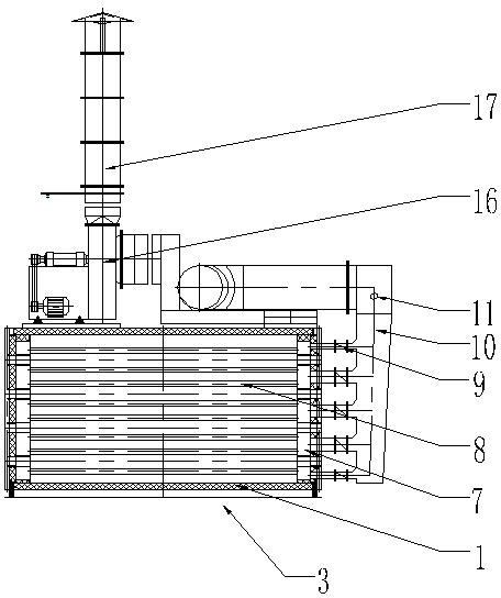
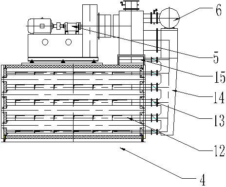
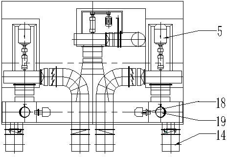
[0019] According to attached figure 1 To attach Figure 7 As shown, the preferred embodiment of the present invention includes a dryer 1, wherein the dryer 1 includes a four-layer roller drying channel 2, and a heating mechanism 3, a moisture discharge Mechanism 4, circulation fan 5, kiln waste heat main pipe 6, wherein, the inlet of the circulation fan 5 is connected with the dehumidification mechanism 4 and the kiln waste heat main pipe 6 respectively; the outlet of the circulation fan 5 is connected with the heating mechanism 3. The heating mechanism 3 of the present invention includes a heating air box assembly 7, a blowing pipe 8, a heating regulating valve 9, a heating connecting pipe 10, and a thermocouple 11, wherein the heating air box assembly 7 is a plurality of left-right symmetrical Installed on and under the rollers of the roller table drying channel 2; the ...


PUM


Abstract

The invention provides a drying device for an architectural ceramic roller table, which comprises a dryer, wherein the dryer comprises four layers of roller table drying channels; a heat supply mechanism, a de-wetting mechanism, a circulating fan and a kiln waste heat main pipe are arranged on the roller table drying channels; an inlet of the circulating fan is respectively connected to the de-wetting mechanism and the kiln waste heat main pipe; and an outlet of the circulating fan is connected to the heat supply mechanism. By using the drying device, the energy source is fully utilized, the emission is reduced and the quick drying for ceramic raw bricks is realized.

Description

technical field [0001] The invention relates to the technical field of drying equipment, in particular to a roller table drying equipment for architectural ceramics. Background technique [0002] At present, in the production process of domestic architectural ceramics, there is a process of drying ceramic tile bodies. Common drying equipment includes 1-2 layers of dryers. The length of the dryer is generally about 150-250 meters, and the floor area is large. The length of the workshop seriously limits the output and scale of the production line, resulting in a series of problems such as large investment, low production capacity, and high management costs. At the same time, a multi-component air device is installed under the roller of this dryer. The hot air enters the dryer to exchange heat with the adobe, and the waste gas is directly discharged through the humidity exhaust air pipe and the humidity exhaust fan. The humidity of the exhaust gas is relatively high, and the te...

Claims


Application Information

Patent Timeline
Patent Type & Authority Applications(China)
IPC IPC(8): F26B15/00F26B21/02
Inventor 柳丹谭映山
Owner GUANGDONG CHINA KILN TECH CO LTD
Why Eureka
Try Eureka