Limited stroke high-dynamic plane motor

A planar motor, high dynamic technology, applied in electrical components, electromechanical devices, etc., can solve the problems of small output thrust and small stroke, and achieve the effect of improving output thrust, low manufacturing cost and high positioning accuracy

Active Publication Date: 2011-09-14
HARBIN INST OF TECH
View PDF4 Cites 9 Cited by
  • Summary
  • Abstract
  • Description
  • Claims
  • Application Information

AI Technical Summary

Problems solved by technology

[0004] The purpose of the present invention is to solve the problem of small stroke and small output thrust

Method used


Image

  • Limited stroke high-dynamic plane motor
  • Limited stroke high-dynamic plane motor
  • Limited stroke high-dynamic plane motor

Examples


specific Embodiment approach 1

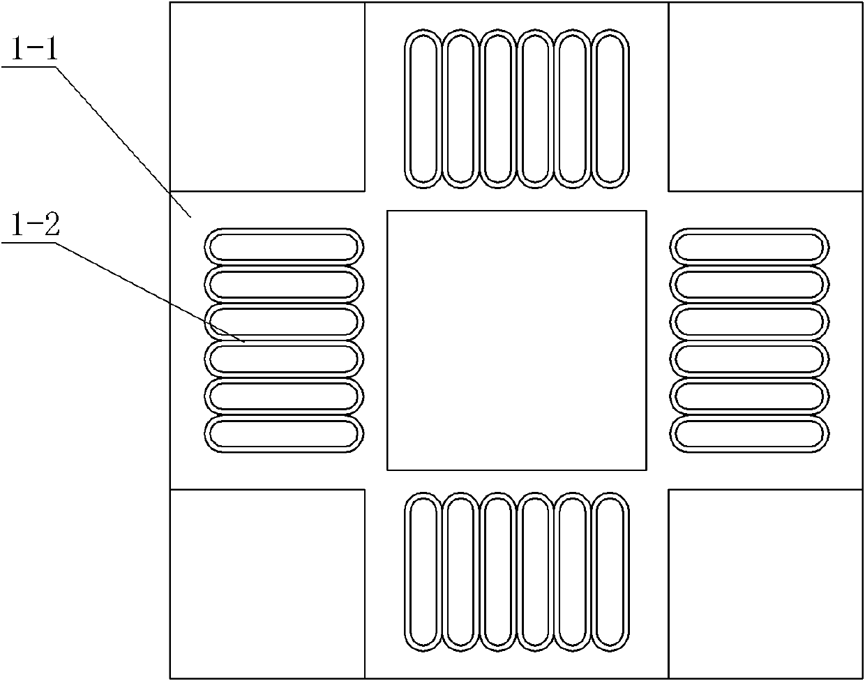
[0023] Specific implementation mode one: the following combination Figure 1 to Figure 3 Describe this embodiment. The limited stroke high dynamic planar motor in this embodiment includes a motor unit and a mover support mechanism. The motor unit includes a motor primary and a motor secondary. The motor unit is a short motor primary and a long motor secondary. structure, there is an air gap between the motor primary and the motor secondary,

[0024] The primary of the motor is a coreless structure, which consists of a winding fixed support plate 1-1 and four armature windings 1-2. The winding fixed support plate 1-1 is a square structure, and each armature winding 1-2 is fixed in the center On a square frame of the fixed support plate 1-1, the four armature windings 1-2 are in the same plane, and each armature winding 1-2 is a symmetrical multi-phase winding composed of a group of coils, and each armature winding The effective side of the coil of 1-2 is perpendicular to the s...

specific Embodiment approach 2

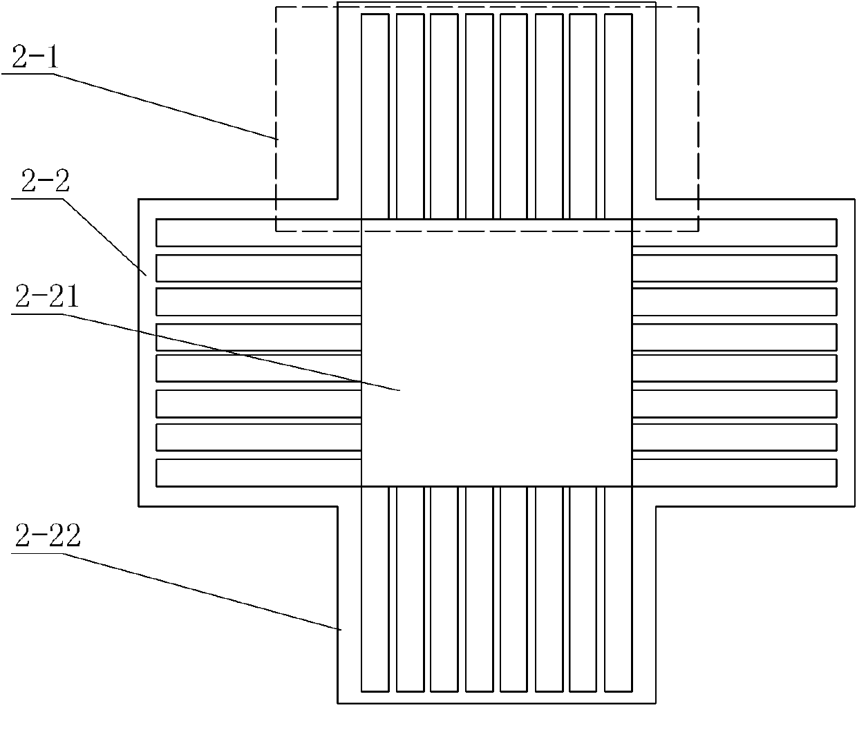
[0029] Specific implementation mode two: the following combination Figure 4 Describe this embodiment. The difference between this embodiment and Embodiment 1 is that the motor secondary also includes a plurality of horizontally magnetized elongated permanent magnets 3, and in each permanent magnet array 2-1, adjacent A horizontally magnetized strip-shaped permanent magnet 3 is arranged between two vertically magnetized strip-shaped permanent magnets, and the magnetization direction of the horizontally magnetized strip-shaped permanent magnet 3 is parallel to the plane where the primary motor is located. And the elongated permanent magnet of vertical magnetization of outward magnetization points to the elongated permanent magnet of vertical magnetization of inward magnetization, and described inward magnetization refers to that the magnetization direction is controlled by the secondary permanent magnet yoke The plate 2-2 points to the primary, and the outward magnetization mea...

specific Embodiment approach 3

[0031] Specific implementation mode three: the following combination Figure 5 Describe this embodiment, the difference between this embodiment and Embodiment 1 is that the motor secondary also includes a plurality of auxiliary permanent magnets 4 and a plurality of concentrating magnets 5,

[0032] The cross-section of the auxiliary permanent magnet 4 is a left-right symmetrical shape, and the cross-section of the concentrating magnet 5 is a left-right symmetrical shape,

[0033] A concentrating magnet 5 is fixedly connected to the air gap side end face of each vertically magnetized elongated permanent magnet, and the concentrating magnet 5 is located in the middle position along the moving direction of the vertically magnetized elongated permanent magnet. An auxiliary permanent magnet 4 is fixed between adjacent two vertically magnetized elongated permanent magnets, and the auxiliary permanent magnet 4 fills up the space formed by its adjacent two vertically magnetized elong...


PUM


Abstract

The invention relates to a limited stroke high-dynamic plane motor which belongs to the technical field of motors. The invention solves the problems of small stroke and small output thrust of the traditional synchronous short-stroke plane motor. The limited stroke high-dynamic plane motor comprises a motor unit and a rotor support mechanism, wherein the motor unit comprises a motor primary class and a motor secondary class; the motor unit has a short motor primary class and long motor secondary class structure; an air gap is arranged between the motor primary class and the motor secondary class; the motor primary class has an iron core-free structure and comprises a winding fixed support plate and four armature windings; the winding fixed support plate has a lip-rounding structure; each armature winding is correspondingly and centrally fixed on a lip-rounding frame of the fixed support plate, the four armature windings are positioned on the same plane, each armature winding is a symmetrical multiphase winding formed by a group of coils; the effective edge of the coil of each armature winding is perpendicular to the lip-rounding frame of the fixed support plate; and the motor secondary class has a double-edge structure and is symmetrically arranged at both sides of the motor primary class. The limited stroke high-dynamic plane motor is used as a plane motor.

Description

technical field [0001] The invention relates to a limited-stroke high-dynamic planar motor, which belongs to the technical field of motors. Background technique [0002] Modern precision and ultra-precision processing equipment has an urgent need for high-response, high-speed, high-precision planar drive devices, such as machining, electronic product production, mechanical loading and unloading, manufacturing automated instrumentation equipment, and even robot drives. Usually these devices are powered by a rotary motor, and then converted into linear motion by mechanical devices such as belts and ball screws. Due to the complex structure of the mechanical device, the transmission accuracy and speed are limited, and frequent adjustments are required, resulting in high cost, poor reliability, and large volume defects. The original planar driving device was realized by using two direct-driven linear motors, which used a stacked driving structure, which increased the complexity...

Claims


Application Information

Patent Timeline
IPC IPC(8): H02K16/02
Inventor 寇宝泉张鲁张赫
Owner HARBIN INST OF TECH
Why Eureka
Try Eureka