Method for automatically compensating bias voltage of QPSK (quadri phase shift keying) lithium niobate modulator

An automatic compensation and modulator technology, applied in the field of signal transmission, can solve the problems of unstable working state, affecting the amplitude and phase of the output signal of the transmitter, affecting the quality of the optical signal, etc., to achieve the effect of good quality and stable signal

Active Publication Date: 2014-01-01
WUHAN POST & TELECOMM RES INST CO LTD
View PDF6 Cites 0 Cited by
  • Summary
  • Abstract
  • Description
  • Claims
  • Application Information

AI Technical Summary

Problems solved by technology

However, in the application, the working state of the QPSK lithium niobate modulator is not stable enough. With the change of temperature, the half-wave voltage of the QPSK lithium niobate modulator will drift, and the bias operating point will also drift with the change of the ambient temperature. The drift of the bias operating point will affect the amplitude and phase of the output signal at the transmitter, thereby affecting the quality of the output optical signal

Method used


Image

  • Method for automatically compensating bias voltage of QPSK (quadri phase shift keying) lithium niobate modulator
  • Method for automatically compensating bias voltage of QPSK (quadri phase shift keying) lithium niobate modulator
  • Method for automatically compensating bias voltage of QPSK (quadri phase shift keying) lithium niobate modulator

Examples


Embodiment Construction

[0020] Embodiments of the present invention will be described in further detail below in conjunction with the accompanying drawings.

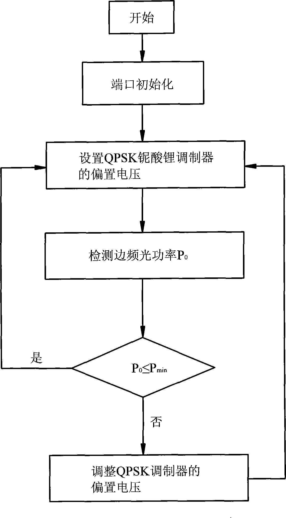
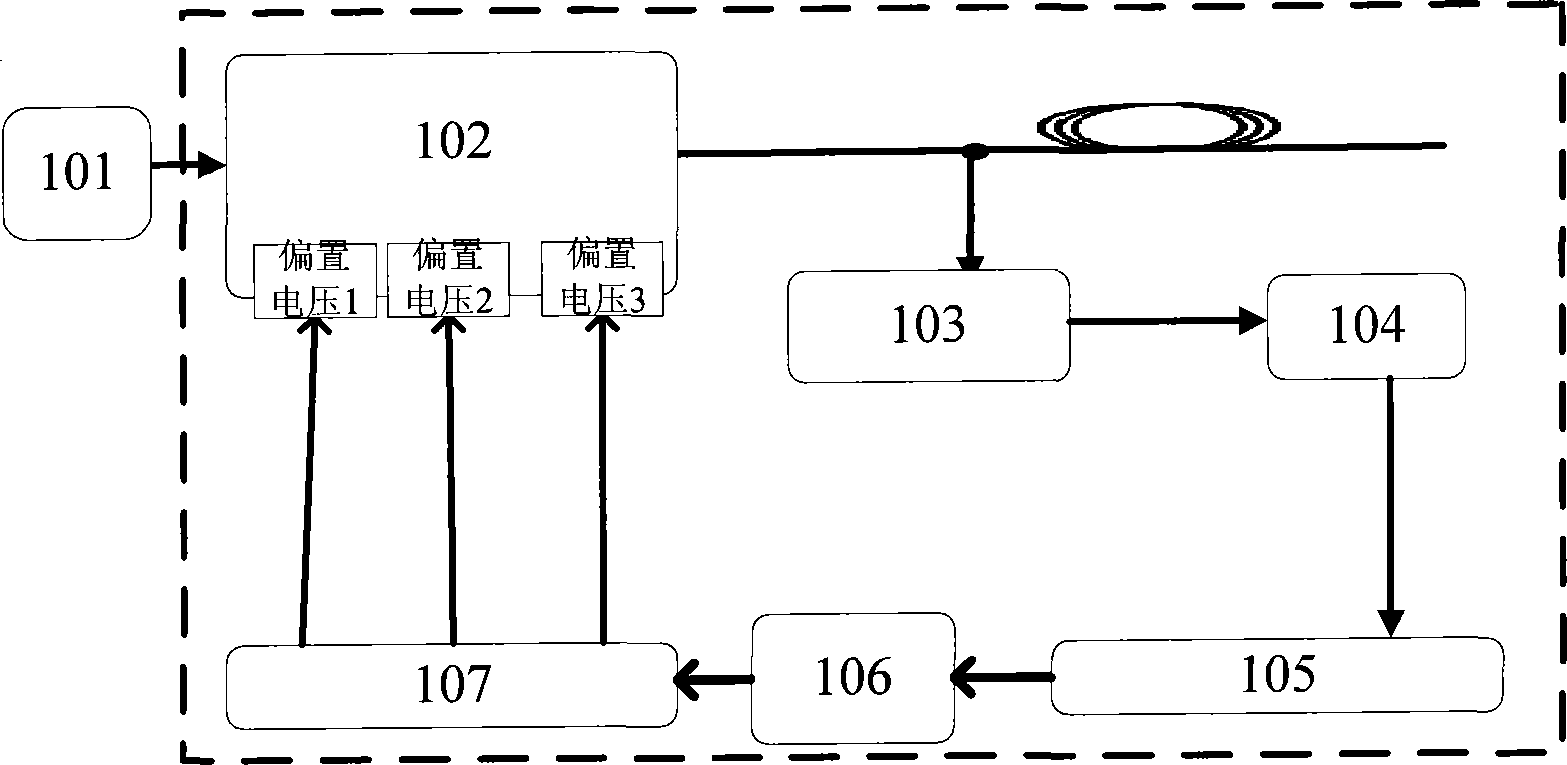
[0021] Such as figure 1 with figure 2 Shown, the present invention automatically compensates the method for QPSK lithium niobate modulator bias voltage, comprises the steps:

[0022] (1) Perform port initialization settings.

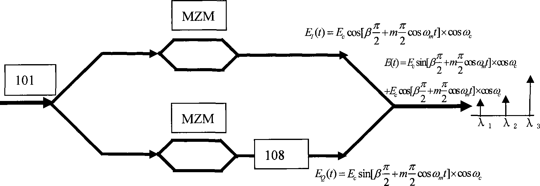
[0023] (2) Set the bias voltage (1, 2, 3) of the QPSK lithium niobate modulator. Both arms of the QPSK lithium niobate modulator are equipped with Mach-Zehnder modulators (abbreviated as MZM). In this embodiment, bias voltage 1 and bias voltage 2 are applied to the MZMs of the two arms, and bias voltage 3 is applied to the MZMs of the two arms. A phase modulator 108. By loading the same radio frequency signal (that is, the signal input from the transmitting end) to the MZM of the two arms, two identical optical signals are generated, and one of the optical signals passes through the phase modulator 108 for a Phase-...


PUM


Abstract

The invention discloses a method and device for automatically compensating bias voltage of a QPSK (quadri phase shift keying) lithium niobate modulator, relating to the field of signal transmission. The method comprises the following steps of: (1) initializing a port; (2) setting the bias voltage of the QPSK lithium niobate modulator; (3) filtering the basic frequency of optical signals output by the QPSK lithium niobate modulator, and detecting the side frequency light power; (4) comparing the detected side frequency light power with minus 45 dbm, if the detected side frequency light power is smaller or equal to minus 45 dbm, returning to the step (2), and if the detected side frequency light power is larger than minus 45 dbm, adjusting the bias voltage of the QPSK lithium niobate modulator; and (5) returning to the step (2) after the bias voltage of the QPSK lithium niobate modulator is adjusted, repeating the steps, and stopping repeating when the detected side frequency light power is smaller or equal to minus 45 dbm for three times continuously. The method disclosed by the invention ensures that a bias working point can be compensated in time when shifting along with temperature change, and thus higher-quality and stable optical signals are output.

Description

technical field [0001] The invention relates to the field of signal transmission in an optical transmission system, in particular to a method and device for automatically compensating the bias voltage of a QPSK lithium niobate modulator. Background technique [0002] With the rapid development of high-speed Internet, video services, and large-capacity private line services, the demand for network capacity is constantly increasing, driving the development of networks to larger capacity and higher speed. The optical modulator is a key device for high-speed, long-distance optical communication and one of the most important integrated optical devices. Optical modulators at home and abroad have made great progress, and their performance has been continuously improved, not only greatly improving the rate and bandwidth, but also increasing the integration density. In addition, with the continuous improvement of optical modulator technology, many new optical modulation devices and ...

Claims


Application Information

Patent Timeline
Patent Type & Authority Patents(China)
IPC IPC(8): H04L27/20H04B10/00H04B10/25
Inventor 高宇琦杨奇贺志学杨超
Owner WUHAN POST & TELECOMM RES INST CO LTD
Why Eureka
Try Eureka