Atomic oscillator utilizing a high frequency converting circuit and an active, low-integral-number multiplier

a high-frequency conversion circuit and low-integral-number multiplier technology, applied in the field ofatomic oscillators, can solve the problems of increased manufacturing cost, delay in manufacture term, and high cost of varactor diodes, and achieve the effect of improving the performance of atomic oscillators and stable low-frequency modulation signals

Inactive Publication Date: 2001-10-09
FUJITSU LTD
View PDF3 Cites 25 Cited by
  • Summary
  • Abstract
  • Description
  • Claims
  • Application Information

AI Technical Summary

Benefits of technology

Further, the atomic oscillator 1 may include a second frequency divider for dividing in frequency the output of the standard oscillator to produce the low-frequency modulation signal so that a highly stable low-frequency modulation signal can be obtained without using a separate oscillator dedicated for generating the low-frequency modulation signal, thus giving a further contribution to downsizing of the atomic oscillator 1 and improvement of its performance.
In another alternative form, the atomic oscillator 1 may include a l...

Problems solved by technology

However, with the foregoing atomic oscillator 101, since the tank circuits 121, 123 for extracting a multiplied-frequency component from the input signal using a coil (L) and a capacitor (C) are used in order to multiply the output of the VCXO 120, it would be necessary to make tuning in accordance with a selected multiplier, i.e. a natural number, for every tank circuit during the manufacture of the atomic oscillator, causing a delay of term of manufacture and an increase of cost of manufacture.
In addition, the varactor diode 134 i...

Method used


Image

  • Atomic oscillator utilizing a high frequency converting circuit and an active, low-integral-number multiplier
  • Atomic oscillator utilizing a high frequency converting circuit and an active, low-integral-number multiplier
  • Atomic oscillator utilizing a high frequency converting circuit and an active, low-integral-number multiplier

Examples


Embodiment Construction

(A) Description of Aspect of the Invention

An aspect of the present invention will now be described with reference to the accompanying drawings.

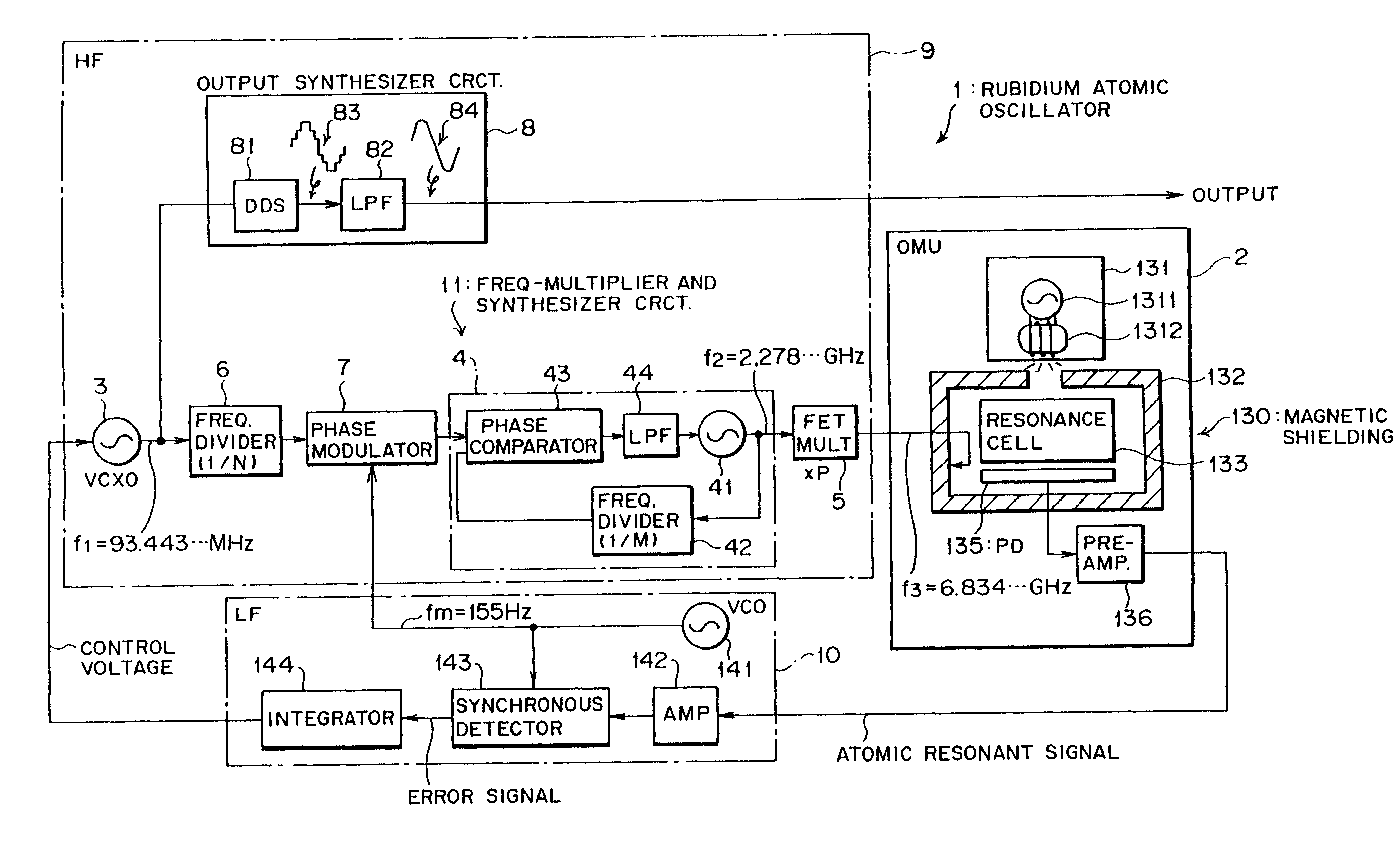
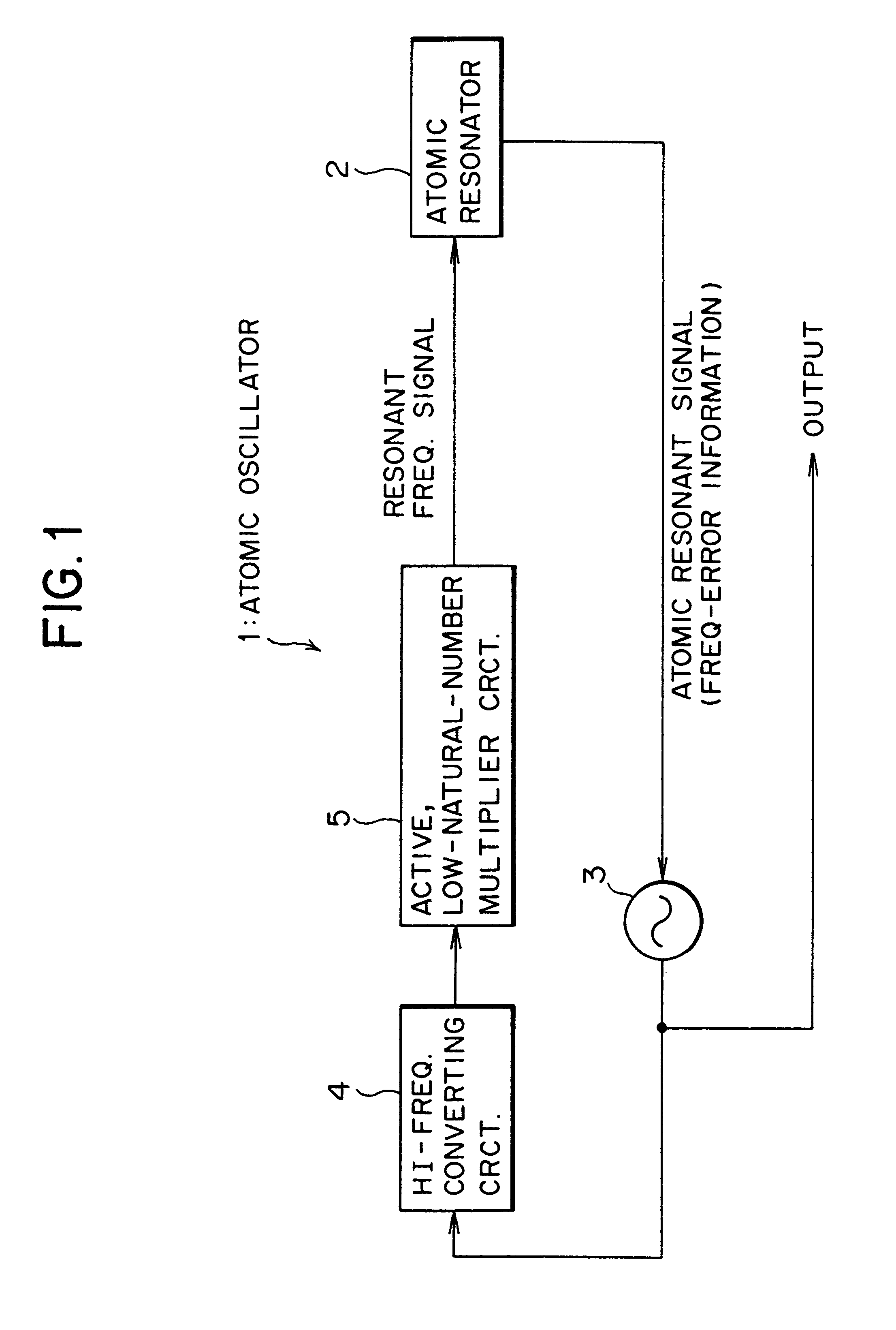
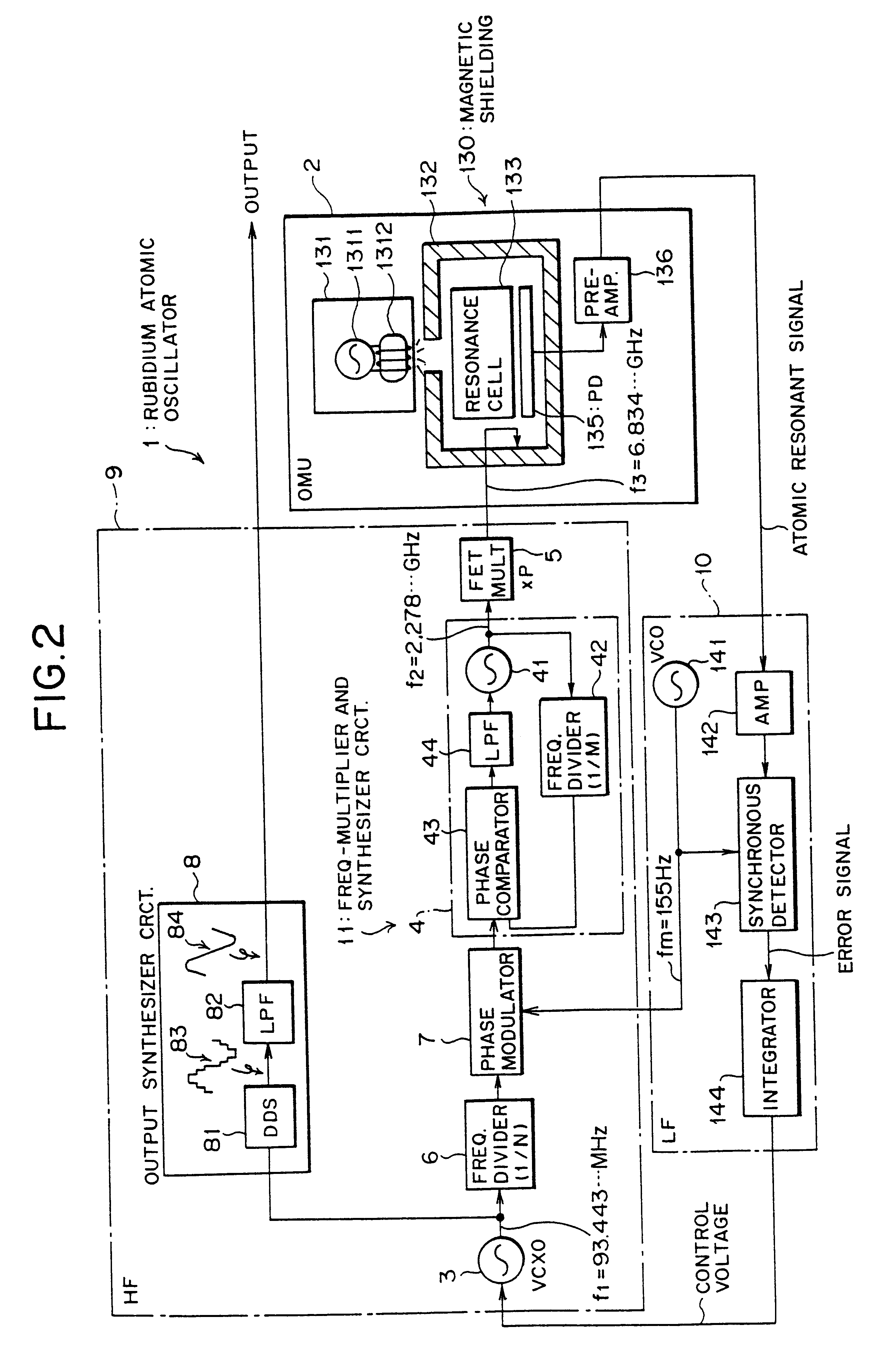
FIG. 1 is a block diagram schematically showing the aspect of the present invention. As shown in FIG. 1, an atomic oscillator 1 of the present invention comprises an atomic resonator 2, a standard oscillator 3, a high-frequency converter circuit 4, and an active, low-natural-number multiplier circuit 5.

The atomic resonator 2 has a desired atom therein and outputs an atomic resonant signal carrying frequency-error information in response to a resonant frequency signal which causes the atom to resonate. The standard oscillator 3 produces an output frequency to be supplied to outside as the output of the atomic oscillator 1, controlling the output frequency in such a manner that the frequency-error information of the atomic resonant signal is minimal.

The high-frequency converter circuit 4 converts the output of the standard oscillator 3 into a h...


PUM


Abstract

In an atomic oscillator, a high-frequency converting circuit converts the output of a standard oscillator into a high frequency signal such that the frequency of the high frequency signal multiplied by a low natural number equals an atomic resonant frequency signal. The high frequency signal is then multiplied by a low natural number in an active, low-natural-number multiplier circuit to convert the output frequency of the standard oscillator into a resonant frequency to be input to the atomic oscillator. The result is that, without using a passive, high-natural-number multiplier circuit, such as a varactor diode, which is expensive, it is possible to convert the output frequency of the standard oscillator into a resonant frequency signal of a rubidium atom, thus downsizing the circuits of the atomic oscillator and reducing the term and cost of manufacture.

Description

1. Field of the InventionThe present invention relates to an atomic oscillator suitable for use as a standard source in broadcasting, a clock source in a digital synchronous network, etc.2. Description of the Related ArtFIG. 6 of the accompanying drawings is a block diagram schematically showing a conventional rubidium atomic oscillator (hereinafter simply called "atomic oscillator"). The atomic oscillator 101 is divided into chiefly three blocks: a high frequency (HF) block 102 as a first block, an optical microwave unit (OMU) 103 as a second block, and a low frequency (LF) block 104 as a third block.The HF block 102 not only generates an output frequency signal to be supplied to outside as the output of the atomic oscillator 101, but also produces from the output frequency signal a signal from which a microwave {rubidium resonant (transitional) frequency signal of approximately 6.8346 GHz} to be produced in the OMU 103 originates. For this purpose, in an example, the HF block 102 ...

Claims


Application Information

Patent Timeline
IPC IPC(8): H03L7/26H01S1/06
CPCH03L7/26
Inventor ATSUMI, KENMATSUURA, HIDEYUKINAKAJIMA, YOSHIFUMIKOYAMA, YOSHITONAKAMUTA, KOJISAKAI, MINORU
Owner FUJITSU LTD
Why Eureka
Try Eureka