
Improved rubidium atomic frequency standard spectral lamp device

A rubidium atomic frequency standard and spectral lamp technology, which is applied in the field of improved rubidium atomic frequency standard spectral lamp device, can solve the problems of reducing optical frequency shift, increasing excitation power, increasing spectral light intensity, etc., to achieve improved stability , Stable working state, the effect of current reduction

Inactive Publication Date: 2011-09-14
JIANGHAN UNIVERSITY
View PDF0 Cites 11 Cited by
  • Summary
  • Abstract
  • Description
  • Claims
  • Application Information

AI Technical Summary

Problems solved by technology

The transistor in this circuit is greatly affected by the ambient temperature. As the ambient temperature rises, the collector current in the transistor will increase, which will lead to an increase in the excitation power, which in turn will lead to an increase in the light intensity of the spectrum lamp. On the contrary, the decrease
The light intensity of the spectral lamp is proportional to the movement of the atomic transition frequency of the rubidium atomic frequency standard, that is, the optical frequency shift. Therefore, when the light intensity increases, the optical frequency shift of the rubidium atomic frequency standard is greater, thus affecting the output frequency of the atomic frequency standard. stability
Since the existing radio frequency oscillation circuit cannot perform temperature compensation to reduce the optical frequency shift, it will affect the output frequency stability of the rubidium atomic frequency standard

Method used


Image

  • Improved rubidium atomic frequency standard spectral lamp device
  • Improved rubidium atomic frequency standard spectral lamp device
  • Improved rubidium atomic frequency standard spectral lamp device

Examples


Embodiment Construction

[0022] Embodiments of the present invention will now be described with reference to the drawings, in which like reference numerals represent like elements.

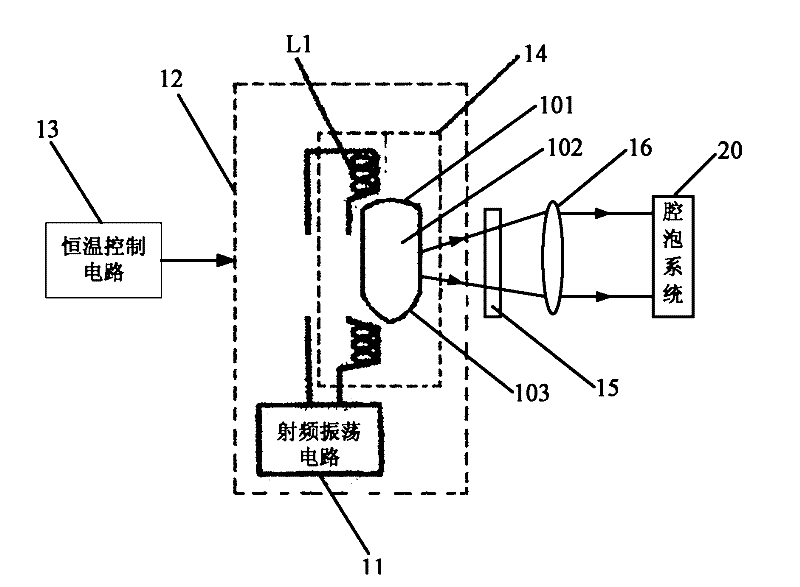
[0023] Such as figure 1 As shown, the improved rubidium atomic frequency standard spectrum lamp device in this embodiment includes a spectrum lamp, a radio frequency oscillation circuit 11 that excites the spectrum lamp to generate pumping light, a thermostat 12 that covers the spectrum lamp, and is used to control the spectrum lamp. The constant temperature cover 12 keeps the constant temperature control circuit 13 of the spectral lamp at a constant temperature, the shielding cylinder cover 14, the neutral filter 15 arranged in front of the spectral lamp, and the neutral filter 15 located in front of the neutral filter 15. Convex lens 16. The light emitted by the spectrum lamp is received by the cavity system 20 after passing through the neutral filter 15 and the convex lens 16 . Preferably, the neutral filter 14 is a ...


PUM


Abstract

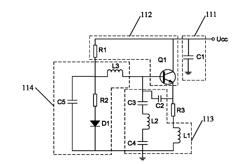
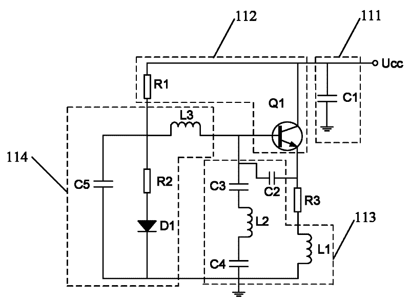
The invention discloses an improved rubidium atomic frequency standard spectral lamp device which comprises a spectral lamp, a radio frequency oscillation circuit, a constant temperature sleeve and a constant temperature control circuit, wherein the radio frequency oscillation circuit comprises a filter circuit, an amplifying circuit, an oscillation frequency selection circuit, a temperature compensation circuit and a feedback resistor which are sequentially connected; the amplifying circuit comprises a transistor and a first bias resistor, wherein the two ends of the first bias resistor are respectively connected with a transistor collector and a transistor base; the temperature compensation circuit is used for reducing the current change of the transistor collector with temperature; one end of the temperature compensation circuit is connected with the first bias resistor, and the other end and a connection point of the transistor base are connected with an input end of the radio frequency oscillation circuit; the feedback resistor is connected in series with the emitter of the transistor; and the transistor and the temperature compensation circuit are located in the same temperature zone. The spectral lamp device disclosed by the invention can improve the stability of the rubidium atomic frequency standard output frequency.

Description

technical field [0001] The invention relates to the field of passive rubidium atomic frequency standards, and more specifically relates to an improved rubidium atomic frequency standard spectral lamp device. Background technique [0002] An atomic frequency standard is a device that provides standard frequency and time. The rubidium atomic frequency standard has become the most widely used atomic frequency standard because of its small size, low power consumption and good ability to withstand harsh environments. It also has good indicators and can meet the needs of most military and civil projects. It can be used in engineering fields such as early warning aircraft, fighter aircraft, electronic countermeasures, third-generation mobile communication technology networks, and power monitoring. [0003] In the rubidium atomic frequency standard, the spectral lamp that generates the pump light is the key component of the atomic frequency standard. The light intensity and spectr...

Claims


Application Information

Patent Timeline
IPC IPC(8): H05B41/36F21V13/00
Inventor 雷海东管桦管妮娜盛荣武
Owner JIANGHAN UNIVERSITY
Learn More