Low-distortion power amplifier system based on peak-clipping circuit

A technology of power amplifier system and peak clipping circuit, which is applied in the direction of transducer circuit, low frequency amplifier, power amplifier, etc., can solve problems such as signal distortion and signal distortion, and achieve the effect of improving quality, avoiding signal distortion, and avoiding excessive peak value

Inactive Publication Date: 2018-02-02
CHENGDU SAIPUQI TECH CO LTD
View PDF0 Cites 0 Cited by
  • Summary
  • Abstract
  • Description
  • Claims
  • Application Information

AI Technical Summary

Problems solved by technology

[0003] The purpose of the present invention is to overcome the defect that the current power amplifier system easily distorts the signal after

Method used


Image

  • Low-distortion power amplifier system based on peak-clipping circuit
  • Low-distortion power amplifier system based on peak-clipping circuit

Examples


Embodiment

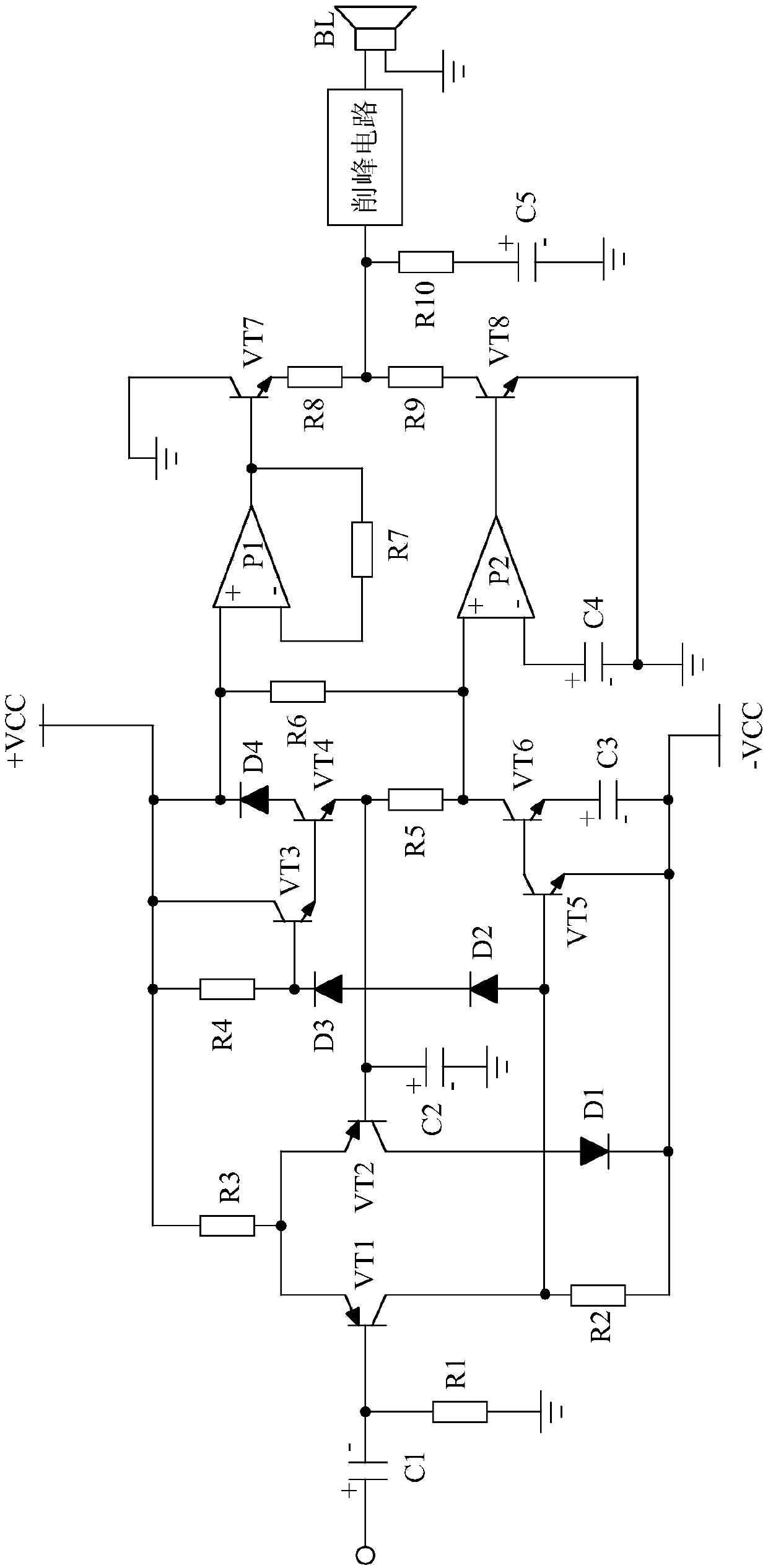
[0015] Such as figure 1 As shown, the present invention mainly consists of a static bias circuit, a power amplifying circuit connected to the static bias circuit, a capacitor C1 whose negative pole is connected to the static bias circuit, and whose positive pole is used as the input end of the power amplifier system, and one end is in phase with the negative pole of the capacitor C1. Connected, the other end of the resistor R1 is grounded, the negative electrode is grounded, the positive electrode is connected to the power amplifier circuit after passing through the resistor R10, and the capacitor C5 is connected to the power amplifier circuit. The input terminal of the low distortion power amplifier system of the present invention is connected with an external signal source.

[0016] Among them, the static bias circuit consists of transistor VT1, transistor VT2, transistor VT3, transistor VT4, transistor VT5, transistor VT6, resistor R2, resistor R3, resistor R4, resistor R5,...


PUM


Abstract

The invention discloses a low-distortion power amplifier system based on a peak clipping circuit, which is characterized in that it mainly consists of a static bias circuit, a power amplifier circuit connected with the static bias circuit, the negative pole is connected with the static bias circuit, and the positive pole is used as Capacitor C1 at the input end of the power amplifier system, one end is connected to the negative pole of capacitor C1, the other end is grounded resistor R1, the negative pole is grounded, the positive pole is connected to the power amplifier circuit after resistor R10, and the capacitor C5 is connected to the power amplifier circuit. The composition of the peak clipping circuit. The invention has a stable static working point, thereby ensuring that the waveform of the amplified signal is the same as that of the signal before amplifying, avoiding signal distortion caused by signal distortion after amplifying, and greatly improving the quality of sound playback.

Description

technical field [0001] The invention relates to a power amplifier system, in particular to a low-distortion power amplifier system based on a peak clipping circuit. Background technique [0002] The power amplifier system is the most basic equipment in the audio system. Its task is to amplify the weak electrical signal from the signal source to drive the speaker to emit sound. However, there is a big problem in the existing power amplifier system, that is, the amplified signal tends to be distorted to varying degrees, which leads to signal distortion and seriously affects the auditory effect. Contents of the invention [0003] The purpose of the present invention is to overcome the defect that the current power amplifier system easily distorts the signal after amplifying the signal, resulting in signal distortion, and provides a low-distortion power amplifier system based on a peak clipping circuit. [0004] The purpose of the present invention is achieved with the follow...

Claims


Application Information

Patent Timeline
IPC IPC(8): H03F1/32H03F3/181H03F3/20H04R3/00
CPCH03F1/32H03F3/181H03F3/20H03F2200/03H04R3/00
Inventor 余泓德
Owner CHENGDU SAIPUQI TECH CO LTD
Why Eureka
Try Eureka