
Pneumatic Brake Cylinder

A pneumatic brake and brake cylinder technology, which is applied in the direction of brake cylinder, brake actuator, engine components, etc., can solve the problem of high installation cost, and achieve the effect of saving installation cost, reducing installation cost and simplifying installation

Active Publication Date: 2016-05-25
KNORR BREMSE SYST FUR SCHIENENFAHRZEUGE GMBH
View PDF6 Cites 0 Cited by
  • Summary
  • Abstract
  • Description
  • Claims
  • Application Information

AI Technical Summary

Problems solved by technology

Therefore, relatively high installation costs when overhauling brake cylinders

Method used


Image

  • Pneumatic Brake Cylinder
  • Pneumatic Brake Cylinder
  • Pneumatic Brake Cylinder

Examples


Embodiment Construction

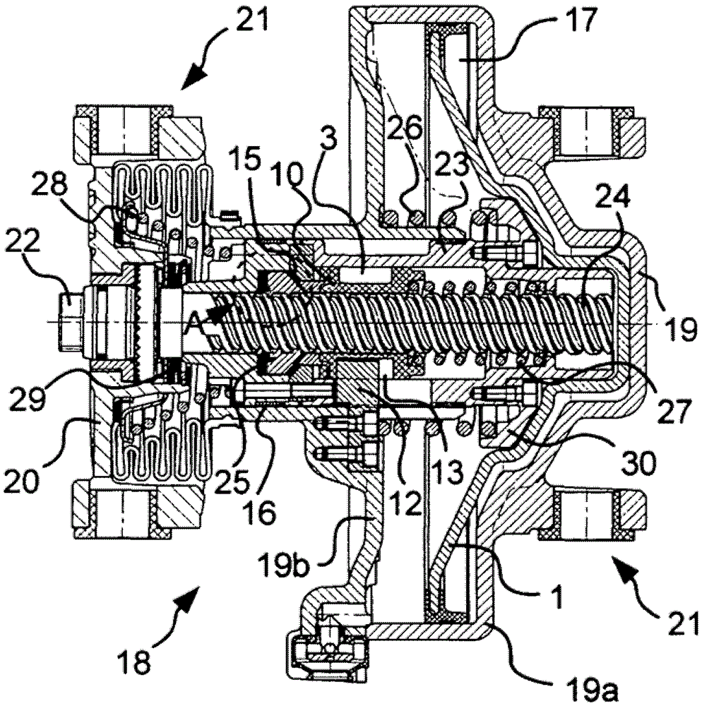
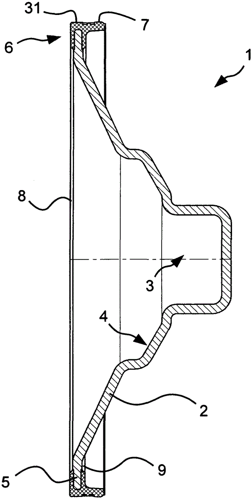
[0020] Figure 4 The new piston 1 shown is designed as a deep-drawn part 2 and is made of sheet steel. In the middle of the piston 1 there is a piston tube receptacle 3, by means of which the piston 1 is placed on the figure 1 On the piston tube 23 shown. There is no direct connection between the piston tube receptacle 3 and the piston tube 23 . Instead, the piston 1 acts on the piston tube 23 via the annular, conically formed contact surface 4 of the piston 1 , and the piston 1 is also centered via the contact surface as soon as the piston 1 is pressurized. In another embodiment not shown here, the piston can also be accommodated by the housing of the brake cylinder and guided through it.

[0021] The sealing ring 6 is vulcanized and bonded to the piston rim 5 . The sealing ring is L-shaped, one of its legs enclosing the piston lip 5 in a groove-like manner. The groove formed in the sides is delimited by a lower lip 8 and an upper lip 9 . The lower lip 8 and the upper l...


PUM


Abstract

The invention relates to a pneumatic brake cylinder including a piston for transferring the pneumatic pressure to a brake, a pressure chamber defined by the piston and part of the inner wall of the brake cylinder, and a sealing ring sealing a gap between the piston and the inner wall of the brake cylinder. According to the invention, the sealing ring is vulcanised onto the piston.

Description

technical field [0001] The invention relates to a pneumatic brake cylinder. Background technique [0002] Such brake cylinders are used in particular in rail vehicles. There, the brake cylinder is usually used to actuate a brake caliper and with its aid press the brake pads onto the brake disc. [0003] A piston is arranged in these pneumatic brake cylinders, which together with the inner wall of the brake cylinder forms a pressure chamber. The gap between the piston and the inner wall of the brake cylinder must be sealed by a sealing ring in order to be able to build up the corresponding pneumatic pressure in the pressure chamber. The sealing ring is usually formed as a separate part and is connected to the piston by a press fit or also by screws. When the sealing ring is connected with the piston by pressing fit, a steel ring is vulcanized and solidified in the sealing ring. In order to ensure a press fit, the piston must also be specially machined at the press fit pos...

Claims


Application Information

Patent Timeline
Patent Type & Authority Patents(China)
IPC IPC(8): B60T17/08F16D65/56F16J15/32F16D65/18F16D65/28
CPCB60T17/08F16D65/56F16D2121/02F16D2125/06
Inventor M-G·埃尔斯托尔普夫C·艾布纳M·玛蒂厄E·福德雷尔
Owner KNORR BREMSE SYST FUR SCHIENENFAHRZEUGE GMBH
Learn More