Riveting machine

A technology for riveting machines and crimping parts is applied in the field of riveting machines that can be automatically oiled, and can solve problems such as low production efficiency, affecting the quality of riveting, and excessive lubricating oil.

Inactive Publication Date: 2011-09-21
KANGZHUN ELECTRONICS TECH KUNSHAN +1
View PDF6 Cites 1 Cited by
  • Summary
  • Abstract
  • Description
  • Claims
  • Application Information

AI Technical Summary

Problems solved by technology

However, when applying lubricating oil manually, it is necessary to apply oil to the gasket and riveting. The operation is

Method used


Image

  • Riveting machine
  • Riveting machine
  • Riveting machine

Examples


Embodiment Construction

[0044] The riveting machine provided by the embodiment of the present invention will be further described in detail below with reference to specific implementation methods and drawings.

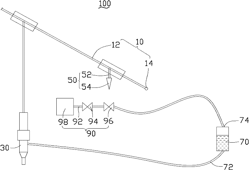
[0045] see figure 1 , The riveting machine 100 according to the embodiment of the present invention includes a pusher 10 , a crimping member 30 , a trigger 50 , an oil storage member 70 and an air delivery assembly 90 .

[0046] The pusher 10 is used to drive the crimping member 30 to move. In this embodiment, the riveting machine 100 is a manual riveting machine, and the pusher 10 is a lever structure, which includes a rod 12 and a rotating shaft 14 at one end of the rod 12 . The rotating shaft 14 is rotatably disposed on the workbench (not shown).

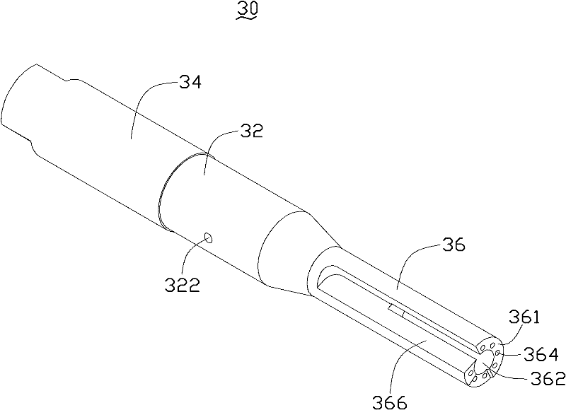
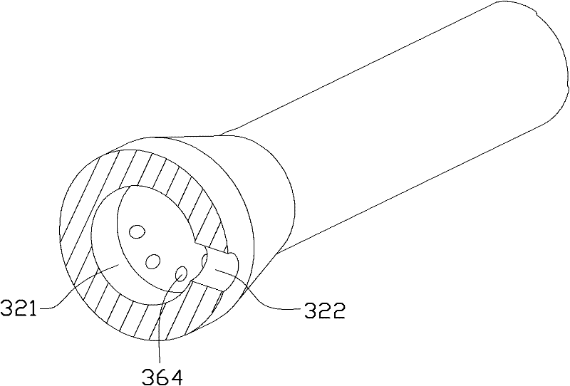
[0047] Please also see figure 2 and image 3 , The crimping member 30 includes a main body portion 32 , an assembly portion 34 and a pressure head 36 . The main body 32 is generally cylindrical, and a cavity 321 is formed therein. The main...


PUM


Abstract

The invention discloses a riveting machine. The riveting machine comprises a pressure welding piece, a trigger piece, an oil storage piece, an oil conveying pipe, an air conveying pipe, a driving pressure welding piece, and a pushing piece, wherein the pressing welding piece includes a main body part, a pressure head and an assembly part, the main body part is cylindric and the pressure head is columnar, the main body part forms a cavity and an oil transportation hole; the pressure head is provided with an oil outlet which runs through the pressure head and extends to the cavity and is communicated with the oil transportation hole; the oil transportation hole is connected with the oil storage piece through the oil conveying pipe; an airflow switch is arranged on an air conveying pipe and one end of the air conveying pipe is connected with the oil storage piece; pushing piece includes a rod part and a rotating shaft; the trigger piece includes a fixed end and a support end, the fixed end is fixedly connected to the rod part, one end of the assembly part far away from the main body part is fixedly connected to the rod part; the trigger piece corresponds to the airflow switch; the support end is driven by the pushing piece to trigger the airflow switch to ensure that air enters the oil storage piece so as to convey the oil in the oil storage piece to the oil outlet, and the support end of the trigger piece is separated from the airflow switch to ensure that the airflow switch is switched off to prevent the oil in the oil storage piece from flowing into the oil outlet. The riveting machine can realize automatic oil removal and has high production efficiency.

Description

technical field [0001] The invention relates to a riveting machine, in particular to a riveting machine capable of automatic oiling. Background technique [0002] During the assembly process of the hinge, it is necessary to sequentially assemble a plurality of gaskets on the rotating shaft of the hinge and use a riveting machine to rivet the two gaskets together. The traditional riveting machine cannot automatically apply lubricating oil during the riveting process, so during the assembly process, the surface of the gasket is applied manually with lubricating oil. However, when applying lubricating oil manually, it is necessary to apply oil to the gasket and riveting. The operation is cumbersome and the production efficiency is low. This not only causes waste but also may affect the quality of riveting. Contents of the invention [0003] In view of the above-mentioned situation, it is necessary to provide a riveting machine that can automatically oil. [0004] A rivetin...

Claims


Application Information

Patent Timeline
IPC IPC(8): B21J15/10B21J3/00
Inventor 张振洲覃芝松于洋
Owner KANGZHUN ELECTRONICS TECH KUNSHAN
Why Eureka
Try Eureka