Revolving cutting tool

A cutting tool and tool technology, which is applied in the direction of manufacturing tools, metal processing equipment, milling machine equipment, etc., can solve the problem of sufficient cutting discharge performance of rotary cutting tools, and achieve the effect of excellent practicability, improved cutting discharge performance, and large effect.

Active Publication Date: 2011-09-21
UNION TOOL
View PDF7 Cites 6 Cited by
  • Summary
  • Abstract
  • Description
  • Claims
  • Application Information

AI Technical Summary

Problems solved by technology

[0004] However, although the above-mentioned chip breaker is provided to improve the cutting discharge performance, it cannot be said that the existing rotary cutting tool can obtain sufficient cutting discharge performance, and the current situation is to further improve the cutting discharge performance.

Method used


Image

  • Revolving cutting tool
  • Revolving cutting tool
  • Revolving cutting tool

Examples


Embodiment Construction

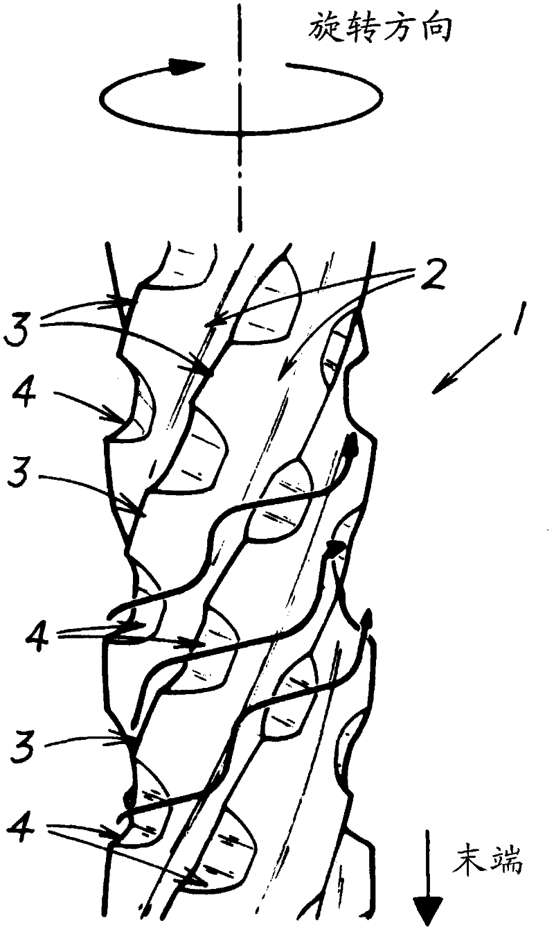
[0030] The action of the present invention will be shown with reference to the drawings, and preferred embodiments of the present invention will be briefly described.

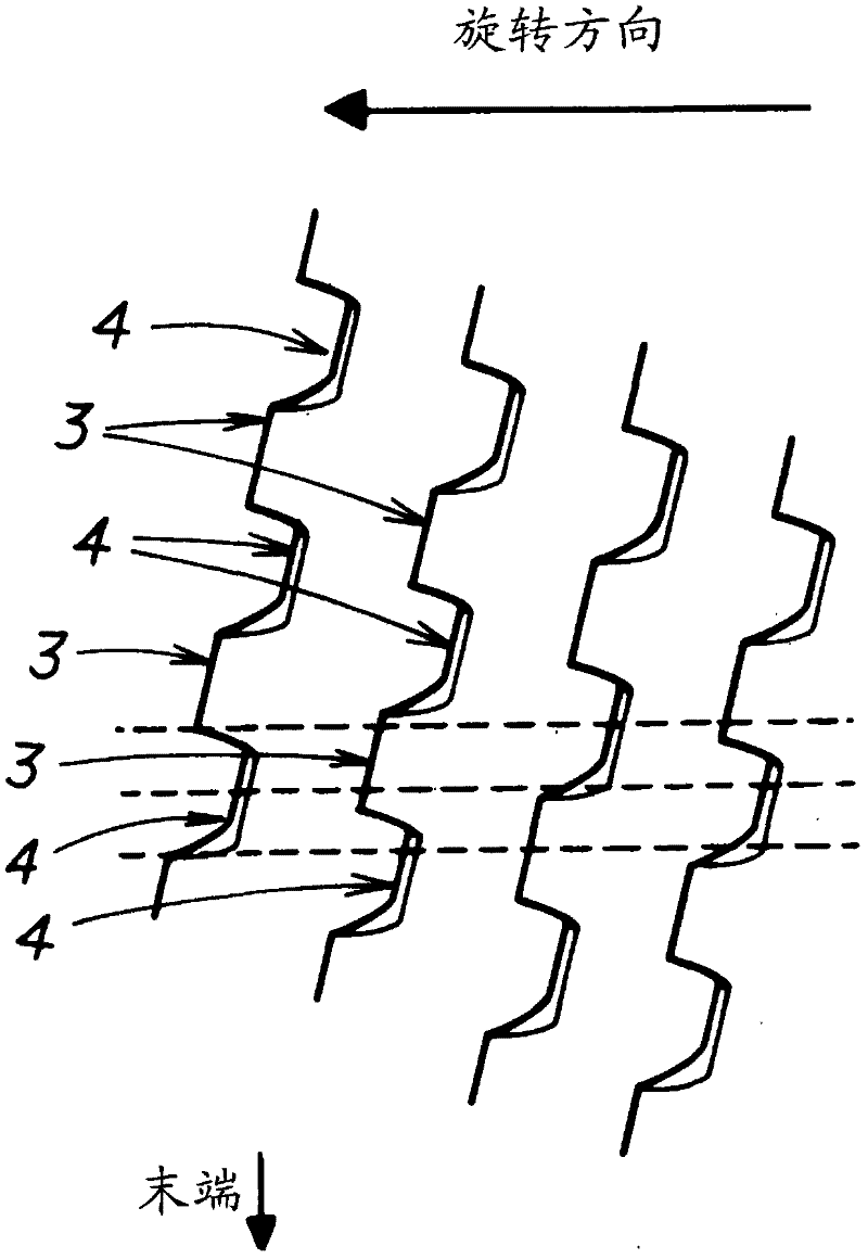
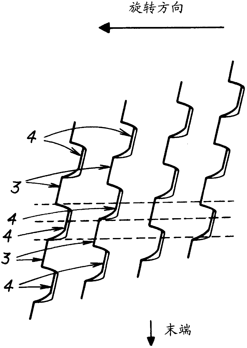
[0031] When the outer peripheral cutting edge 3 of the rotating tool body 1 is brought into contact with the workpiece to cut the workpiece, the chips move in a predetermined direction (upward or downward) through the chip removal groove 2 , while part of the chips move toward the workpiece through the chip breaker 4 . The chip flute 2 adjacent to the rear side moves in the direction of tool rotation.

[0032] At this time, if the rotation trajectory of the outer peripheral cutting edge 3 adjacent to the rear side of the chip breaker 4 in the tool rotation direction overlaps with a part of the rotation trajectory of the chip breaker 4 by a ratio of 40% or more, as figure 1 As shown in the figure, chips passing through the chip breaker 4 are likely to come into contact (collision) with (the rake face of) the out...


PUM


Abstract

The invention provides a revolving cutting tool which is extremely high in effect of cutting discharge performance improvement caused by a chip breaker groove and excellent in practicability. A plurality of spiral chip grooves (2) extending from the tail end of the tool toward the base end side thereof are formed at the outer periphery of a tool body (1); an outer peripheral cutting edge (3) is formed on a cross ridge portion of the anteverted face of the spiral chip groove (2) which intersects with the outer peripheral surface of the tool body (1) or on a cross ridge portion thereof which intersects with an outer peripheral rear gap surface formed at the outer periphery of the tool body (1); and a plurality of chip breaker grooves (4) are formed in the outer peripheral surface of the tool body (1) or in the outer peripheral rear gap surface in a manner of dividing the outer peripheral cutting edge (3), wherein the revolving cutting tool is so structured that the revolving track of the outer peripheral cutting edge (3) adjacent to the rear side of the tool revolving direction of the chip breaker groove (4) is coincident with a portion of the revolving track of the chip breaker groove (4) in a portion of 40% or higher.

Description

technical field [0001] The present invention relates to a rotary cutting tool. Background technique [0002] As rotary cutting tools such as routers used in the processing of printed circuit boards and end mills used in the processing of metal materials, for example, as disclosed in Patent Document 1, there are A rotary cutting tool is provided with a chip breaker for dividing the peripheral cutting edge on the peripheral relief surface of the tool. [0003] Patent Document 1: Japanese Patent Laid-Open No. 2008-114308 [0004] However, although the above-mentioned chip breaker is provided to improve the cutting discharge performance, it cannot be said that the conventional rotary cutting tool can obtain sufficient cutting discharge performance, and the current situation is to further improve the cutting discharge performance. Contents of the invention [0005] In view of the above-mentioned present situation, the inventors of the present invention conducted various resea...

Claims


Application Information

Patent Timeline
IPC IPC(8): B23C5/10
Inventor 佐藤将靖高桥宏美
Owner UNION TOOL
Why Eureka
Try Eureka