Waveform heat transfer element of heat exchanger
A technology of heat transfer elements and heat exchangers, which is applied in the field of wave heat transfer elements of heat exchangers, can solve the problems of low heat transfer efficiency, high cost, and huge outsourcing workload of heat exchangers, etc., and achieve high heat exchange efficiency , low running resistance, conducive to the effect of online cleaning
Inactive Publication Date: 2011-09-21
JIANGSU JINYANG ENERGY & ENVIRONMENT ENG
View PDF8 Cites 0 Cited by
- Summary
- Abstract
- Description
- Claims
- Application Information
AI Technical Summary
Problems solved by technology
The defect of the compact shape is that the waveform is compact. Although it has a high heat transfer efficiency, it brings the problem of clogging after operation. The defect of the high waveform is that the heat transfer efficiency is low, which makes the heat exchanger a huge workload and high cost.
Method used
View moreImage
Smart ImageViewing Examples

Examples
Embodiment Construction
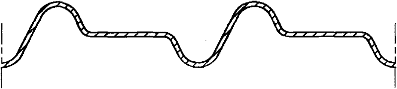
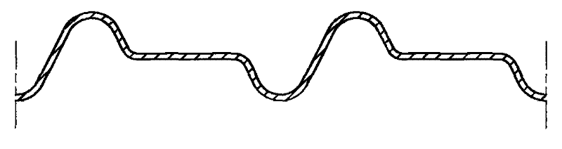
[0008] like figure 1 As shown, a corrugated heat transfer element of a heat exchanger of the present invention is formed by pressing a steel plate coated with high-quality heat-resistant enamel; a flat surface is formed between the pressed "S"-shaped waves, and the flat surface is located in the section " The middle position between the upper and lower vertices of the S-shaped waveform, the pitch between the adjacent "S"-shaped waveform vertices is 30-38mm, and the distance between the upper and lower vertices of the "S"-shaped waveform is 8-12mm.
Login to View More PUM
 Abstract
The invention discloses a waveform heat transfer element of a heat exchanger. The heat transfer element is formed by pressing a steel plate the surface of which is coated with high-quality heat-resisting enamel; a flat and straight surface is manufactured between pressed 'S'-shaped waveforms, and is positioned at the middle position of the upper vertex and lower vertex of the 'S'-shaped cross section; the pitch between adjacent 'S'-shaped vertices is regulated to be 30-38mm; and the distance between the upper vertex and the lower vertex is 8-12mm. The waveform heat transfer element of the heat exchanger provided by the invention is good for on-line cleaning, and has the advantages of high heat transfer efficiency, lower operation resistance, and the like.
Description
technical field [0001] The invention relates to a heat transfer element, in particular to a corrugated heat transfer element of a heat exchanger. Background technique [0002] The heat transfer elements commonly used in general heat exchangers are divided into two categories: compact and high waveform. The defect of the compact shape is that the waveform is compact. Although it has a high heat transfer efficiency, it brings the problem of clogging after operation. The defect of the high waveform is that the heat transfer efficiency is low, which makes the heat exchanger a huge workload and high cost. . Contents of the invention [0003] The problem to be solved by the present invention is to overcome the deficiencies in the background technology and provide a wave heat transfer element of a heat exchanger. This heat transfer element adopts a streamlined wave shape, which can obtain higher heat exchange efficiency and reduce running resistance at the same time. Avoid clog...
Claims
Login to View More Application Information
Patent Timeline
 Patent Type & Authority Applications(China)
IPC IPC(8): F28F13/00
Inventor 邹宇俞根娣王宏伟
Owner JIANGSU JINYANG ENERGY & ENVIRONMENT ENG