Laser cleaning equipment based on fiber laser

A fiber laser and laser cleaning technology, which is applied in the direction of cleaning methods and appliances, chemical instruments and methods, etc., can solve the problems of low cleaning efficiency and high cost, and achieve high cleaning cleanliness and efficiency, no damage to the substrate, and low operation/maintenance costs low effect

Active Publication Date: 2017-04-12
杭州志英光电有限公司
View PDF6 Cites 0 Cited by
  • Summary
  • Abstract
  • Description
  • Claims
  • Application Information

AI Technical Summary

Problems solved by technology

[0006] In order to solve the problems of high cost and low cleaning efficiency of existing laser cleaning equipment, the present invention proposes a laser cleaning equipment based on fiber laser

Method used


Image

  • Laser cleaning equipment based on fiber laser
  • Laser cleaning equipment based on fiber laser
  • Laser cleaning equipment based on fiber laser

Examples


Embodiment Construction

[0021] The present invention will be further described in detail below in conjunction with the accompanying drawings and embodiments.

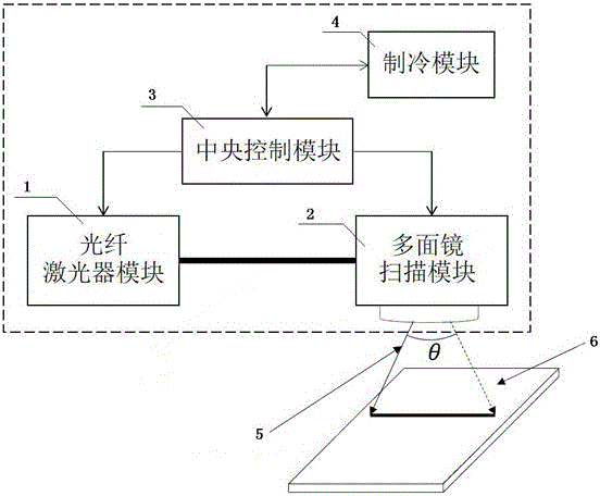
[0022] Such as figure 1 As shown, a laser cleaning device based on a fiber laser is composed of a fiber laser module 1, a polygon mirror scanning module 2, a central control module 3, a cooling module 4 and a power supply module, wherein the power supply module is connected to the fiber laser module, the polygon mirror The scanning module, the central control module, and the refrigeration module are electrically connected, the fiber laser module, the polygon mirror scanning module, and the refrigeration module are respectively electrically connected to the central control module, and the fiber laser module and the polygon mirror scanning module are connected through optical fibers.

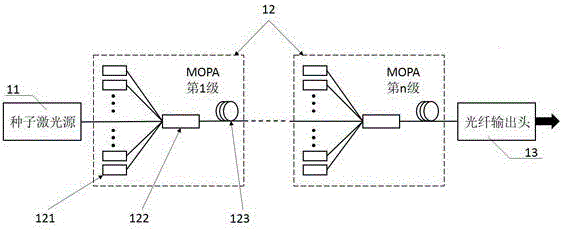
[0023] Such as figure 2 As shown, the fiber laser module includes a seed laser source 11, a power amplifier 12 of a multi-stage master oscillator and an optical...


PUM


Abstract

The invention discloses laser cleaning equipment based on a fiber laser unit. The laser cleaning equipment comprises a fiber laser unit module, a polygonal mirror scanning module, a central control module, a refrigeration module and a power supply module, wherein the power supply module is electrically connected to the fiber laser unit module, the polygonal mirror scanning module, the central control module and the refrigeration module; the fiber laser unit module, the polygonal mirror scanning module and the refrigeration module are electrically connected to the central control module; the fiber laser unit module is connected to the polygonal mirror scanning module through an optical fiber, and a laser beam generated by the fiber laser unit module is transmitted to the polygonal mirror scanning module through the optical fiber. The laser cleaning equipment disclosed by the invention is high in cleaning cleanliness and efficiency; a substrate is not damaged; operation and monitoring are convenient; operation and maintenance cost is low; on-line cleaning is easy; and no secondary pollution is caused.

Description

technical field [0001] The invention relates to a laser cleaning device, in particular to a laser cleaning device based on a fiber laser. Background technique [0002] In production and life, various equipment and products will form or adhere to some harmful pollutants on the surface during production or use, which will seriously affect their surface appearance and performance stability over time. Therefore, some physical and chemical means must be used to remove these pollutants, so that the items can reach the predetermined cleanliness and other performance indicators. [0003] At present, the most commonly used cleaning methods include manual / mechanical friction, chemical cleaning, high-pressure water jet cleaning, shot blasting cleaning and ultrasonic cleaning. The manual / mechanical friction method has the disadvantages of time-consuming and laborious, easy to damage the substrate, and poor working environment; the chemical cleaning method is relatively cheap, but it ha...

Claims


Application Information

Patent Timeline
Patent Type & Authority Patents(China)
IPC IPC(8): B08B7/00B08B13/00
CPCB08B7/0042B08B13/00
Inventor 张卓鹏杨国伟魏一振
Owner 杭州志英光电有限公司
Why Eureka
Try Eureka