Current detector

A technology of current detector and current detection circuit, applied in the direction of voltage/current isolation, measuring current/voltage, instruments, etc., can solve problems such as current detection error, and achieve the effect of reducing current detection error

Inactive Publication Date: 2011-09-21
TAMURA KK
View PDF6 Cites 9 Cited by
  • Summary
  • Abstract
  • Description
  • Claims
  • Application Information

AI Technical Summary

Problems solved by technology

[0003] However, as described above, in a current detector in which a plurality of current sensor circuits are assembled into one set, a plurality of sets of coils and cores must be arranged adjacent to each other in a casing or a housing, and there is leakage magnetic flux from each set of coils or cores. Mutual interference between the current detection error caused by the situation

Method used


Image

  • Current detector
  • Current detector
  • Current detector

Examples


Embodiment 1

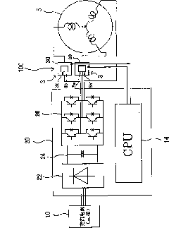
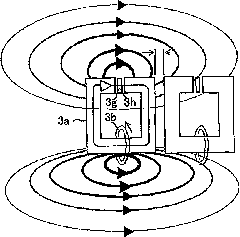
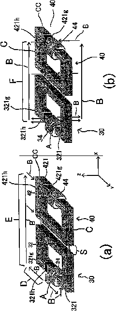
[0046] image 3 and Figure 4 It is a diagram showing a schematic configuration of a current detector according to Embodiment 1 of the present invention. image 3 It is a diagram showing a schematic structure consisting of a core, a coil, and a Hall element. (a) is a diagram showing the core, coil, Hall element, and leakage flux on the XY plane, and (b) is showing the leakage flux on the XZ plane. common diagram. Figure 4 It is a diagram that further includes a schematic structure of a board, embedded pins (On board pins), lead wires, and signal lines. (a) is a diagram showing magnetic flux leakage on the XY plane, and (b) is a diagram showing magnetic flux leakage on the XZ plane. .

[0047] Such as image 3 (a), (b) and Figure 4 As shown in (a) and (b), the current detector of this embodiment has the following configuration: the first current detection circuit 30 and the second current detection circuit 40 are arranged in parallel on a substrate (the substrate of the ...

Embodiment 2

[0058] Figure 5 and Figure 6 It is a diagram showing a schematic configuration of a current detector according to Embodiment 2 of the present invention. Figure 5 It is a diagram showing a schematic structure consisting of a core, a coil, and a Hall element. (a) is a diagram showing the core, coil, Hall element, and leakage flux on the XY plane, and (b) is showing the leakage flux on the XZ plane. common diagram. Figure 6 It is a diagram showing a schematic structure further including a substrate, embedded pins, leads, and signal lines, (a) is a diagram showing leakage flux on the XY plane, and (b) is a diagram showing leakage flux on the XZ plane.

[0059] Such as Figure 5 (a), (b) and Figure 6 As shown in (a) and (b), the current detector of this embodiment has the following structure: the first current detection circuit 50 and the second current detection circuit 60 are formed on a substrate (the substrate of the current detector), a bobbin, a frame or They are ar...

Embodiment 3

[0070] Figure 7 and Figure 8 It is a diagram showing a schematic configuration of a current detector according to Embodiment 3 of the present invention. Figure 7 It is a diagram showing a schematic structure consisting of a core, a coil, and a Hall element. (a) is a diagram showing the core, coil, Hall element, and leakage flux on the XY plane, and (b) is showing the leakage flux on the XZ plane. common diagram. Figure 8 It is a diagram showing a schematic structure further including a substrate, embedded pins, leads, and signal lines, (a) is a diagram showing leakage flux on the XY plane, and (b) is a diagram showing leakage flux on the XZ plane.

[0071] This embodiment is characterized in that the structure of the first embodiment in which the Hall element in the second current detection circuit is separated from the leakage magnetic flux generating part in the first current detection circuit as described above has an angle (θ = 90° °) The structure of embodiment 2 i...


PUM


Abstract

The present invention provides a current detector, wherein a first current detection circuit and a second current detection circuit are configured to a group in a preset space. The first current detection circuit and the second current detection circuit respectively comprise the following components: an annular core; a coil which winds a preset position of the core; and a magnetic inductance component which is configured in a preset position relationship with the coil in a clearance formed by the core, wherein, the coil and the clearance in the first current detection circuit and the second current detection circuit are respectively configured that the orientation of the magnetic induction component in the second current detection circuit has an angle (theta=90 DEG) relatively to the position on the core, which is coiled by the coil in the first current detection circuit, and the position with the clearance.

Description

technical field [0001] The present invention relates to a magnetic proportional current detector used in measuring and detecting current. Background technique [0002] Such a current detector converges a magnetic field generated by a detected current through a core, and converts the magnetic flux into a voltage through a magnetic induction element (for example, a Hall element) disposed between gaps in the core, and outputs it. In addition, for example, an inverter device used for motor control is included as an application of a Hall element type current detector. Recently, not only industrial equipment, but also many consumer equipment (home appliances) are equipped with inverter devices. The installed inverter devices can freely, continuously and efficiently change the rotation speed of the motor inside the equipment, etc., to achieve good operation of the equipment. In addition, as the operation principle of the controlled motor in the equipment, there is a device that ut...

Claims


Application Information

Patent Timeline
Patent Type & Authority Applications(China)
IPC IPC(8): G01R19/00G01R15/20
Inventor 龙末洋小林正和
Owner TAMURA KK
Why Eureka
Try Eureka