Power conversion apparatus and electric power steering apparatus having the same

A technology of power conversion and equipment, applied in the field of electric power steering equipment, can solve problems such as inability to properly perform current detection, and achieve the effect of simple configuration

Active Publication Date: 2015-03-25
DENSO CORP
View PDF3 Cites 14 Cited by
  • Summary
  • Abstract
  • Description
  • Claims
  • Application Information

AI Technical Summary

Problems solved by technology

In the case where the zero voltage vector period is long, such as when the app

Method used


Image

  • Power conversion apparatus and electric power steering apparatus having the same
  • Power conversion apparatus and electric power steering apparatus having the same
  • Power conversion apparatus and electric power steering apparatus having the same

Examples


no. 1 approach

[0037] Figure 1 to Figure 21 A power conversion device according to a first embodiment of the present disclosure and an electric power steering device using the same are shown. Hereinafter, the same reference numerals are used for substantially the same configurations in various embodiments, and descriptions thereof will not be repeated.

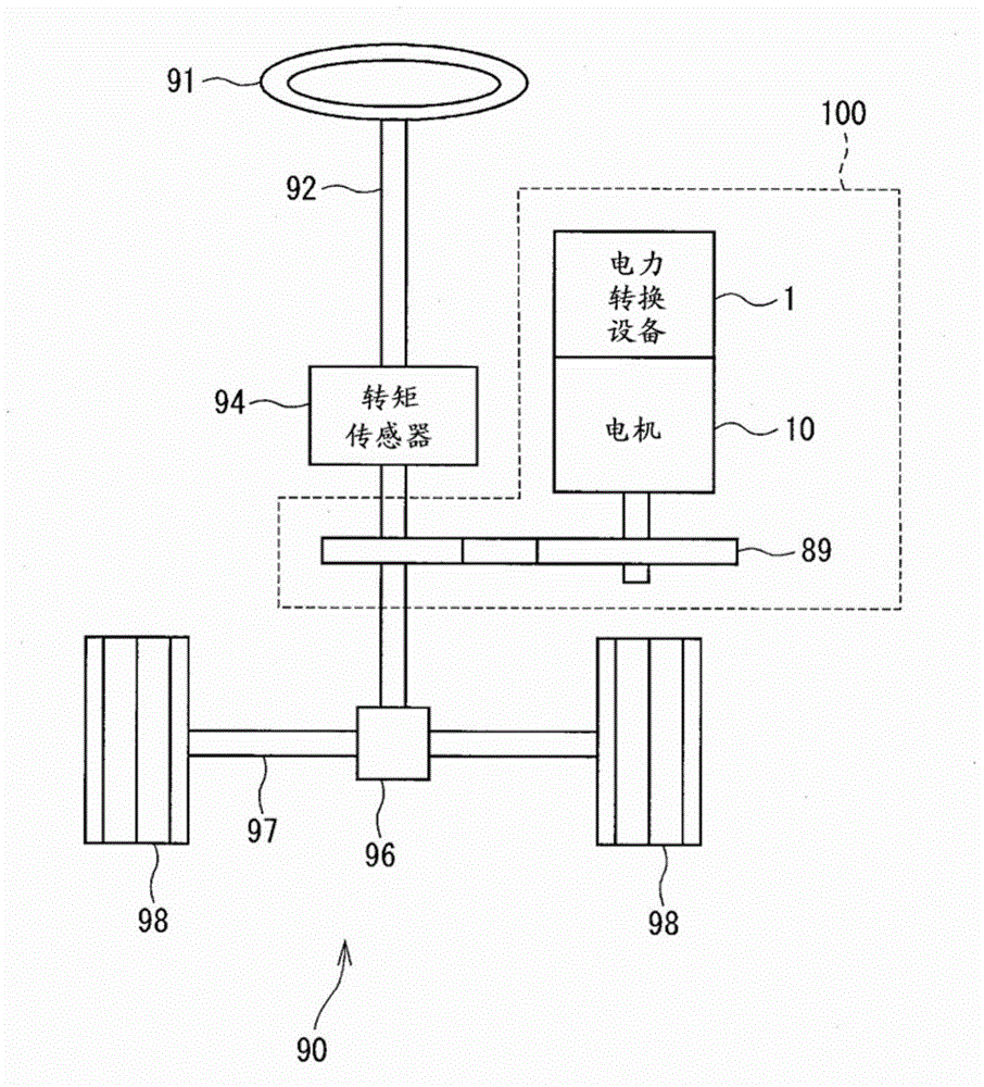
[0038] like figure 1 As shown, the power conversion device 1 is applied to, for example, an electric power steering device 100 for assisting a steering operation of a vehicle together with an electric machine 10 as a rotating electric machine.

[0039] figure 1 An overall configuration of a steering system 90 having an electric power steering apparatus 100 is shown. The steering system 90 is constituted by a handle (steering wheel) 91, a steering shaft 92, a pinion 96, a rack shaft 97, wheels 98, an electric steering apparatus 100, and the like.

[0040] The handlebar 91 is connected to a steering shaft 92 . The steering shaft 92 is pr...

no. 2 approach

[0320] will refer to Figure 22 A second embodiment of the present disclosure is described. Since the second embodiment differs from the first embodiment regarding the current control cycle. Differences will be mainly described.

[0321] In the first embodiment, the currents Iu, Iv, and Iw of the respective phases are calculated every two cycles, and current control is performed.

[0322] like Figure 22 As shown, in the second embodiment, current control is performed every four cycles. Specifically, phase current calculation unit 61 calculates V-phase current Iv based on the average value of current detection values ​​Iv(+) and Iv(−) detected in the second period. Phase current calculation unit 61 also calculates W-phase current Iw based on the average value of Iw(−) and Iw(+) detected in the third period. The U-phase current Iu is calculated by "sum of three phases=0".

[0323] Based on the calculated currents Iu, Iv, and Iw of each phase, calculate the duty ratio comm...

no. 3 approach

[0326] In the foregoing embodiment, the current detection value when correction is made in the positive direction in one PWM period and when The current detection value when correction is made in the negative direction in one PWM cycle, the center current Ia is calculated, and current control is performed based on the center current Ia.

[0327] On the other hand, when the magnitude of the voltage command values ​​Vu*, Vv*, and Vw* is equal to or greater than the first predetermined value THa1, ​​based on the case of correcting the duty ratio to the positive side or the case of correcting the duty ratio to the negative side To calculate the current Iu, Iv and Iw of each phase, so that the distortion of the current waveform cannot be corrected.

[0328] Thus, in the embodiment, the correction factor Y is calculated when the magnitude of the voltage command values ​​Vu*, Vv*, and Vw* is smaller than the first predetermined value THa1. Based on the calculated correction factor Y...


PUM


Abstract

A power conversion apparatus (2) includes: an inverter unit (20) having high and low potential-side switching elements (21-26) corresponding to each phase of a winding (15) of a rotating electrical machine (10); a current detecting unit (40); a current obtaining unit (42) obtaining a current detection value with a fixed interval sampling timing; and a control unit (60) controlling the switching elements based on a PWM reference signal and a duty instruction value. The control unit (60) includes: a phase current computing device; voltage instruction value computing devices (63, 64); and a duty computing device. The phase current computing device computes a correction current based on positive and negative side corrected current detection values. The positive-side corrected current detection value is obtained when a duty is adjusted to a positive side, and the negative-side corrected current detection value is obtained when the duty is adjusted to a negative side.

Description

technical field [0001] The present disclosure relates to a power conversion device and an electric power steering device having the power conversion device. Background technique [0002] In general, an inverter device for detecting current through a current detection device provided for a DC (direct current) portion in an inverter is known. In the case where the currents of the respective phases are detected by the current detection means provided for the DC part in the inverter, it is necessary to detect the currents in the active voltage vector time interval. Therefore, current detection cannot be performed at the peak of the PWM reference signal which is a carrier signal, and a ripple component is included in the current detection value. To solve this problem, for example, in Patent Document 1, times symmetrical with respect to the carrier peak are obtained, the average value is used as the phase current detection value at the carrier peak, and the average value is used ...

Claims


Application Information

Patent Timeline
IPC IPC(8): H02M7/48H02P6/10
CPCB62D5/046H02M7/53875H02M7/5395H02M1/0009B62D5/0472H02M7/53871
Inventor 铃木崇志
Owner DENSO CORP
Why Eureka
Try Eureka