Control device for AC rotary motor and control device for electric power steering system

A technology for rotating electrical machines and control devices, which is applied in AC motor control, control system, motor control and other directions, can solve the problem of phase current value that cannot be detected, and achieve the effect of reducing current detection errors.

Active Publication Date: 2020-07-03
MITSUBISHI ELECTRIC CORP
View PDF7 Cites 0 Cited by
  • Summary
  • Abstract
  • Description
  • Claims
  • Application Information

AI Technical Summary

Problems solved by technology

This conventional motor control device estimates the phase current value of the undetectable phase based on the phase current values ​​of two phases other than the undetectable phase (for example, refer to Patent Document 1).

Method used


Image

  • Control device for AC rotary motor and control device for electric power steering system
  • Control device for AC rotary motor and control device for electric power steering system
  • Control device for AC rotary motor and control device for electric power steering system

Examples


Embodiment approach 1

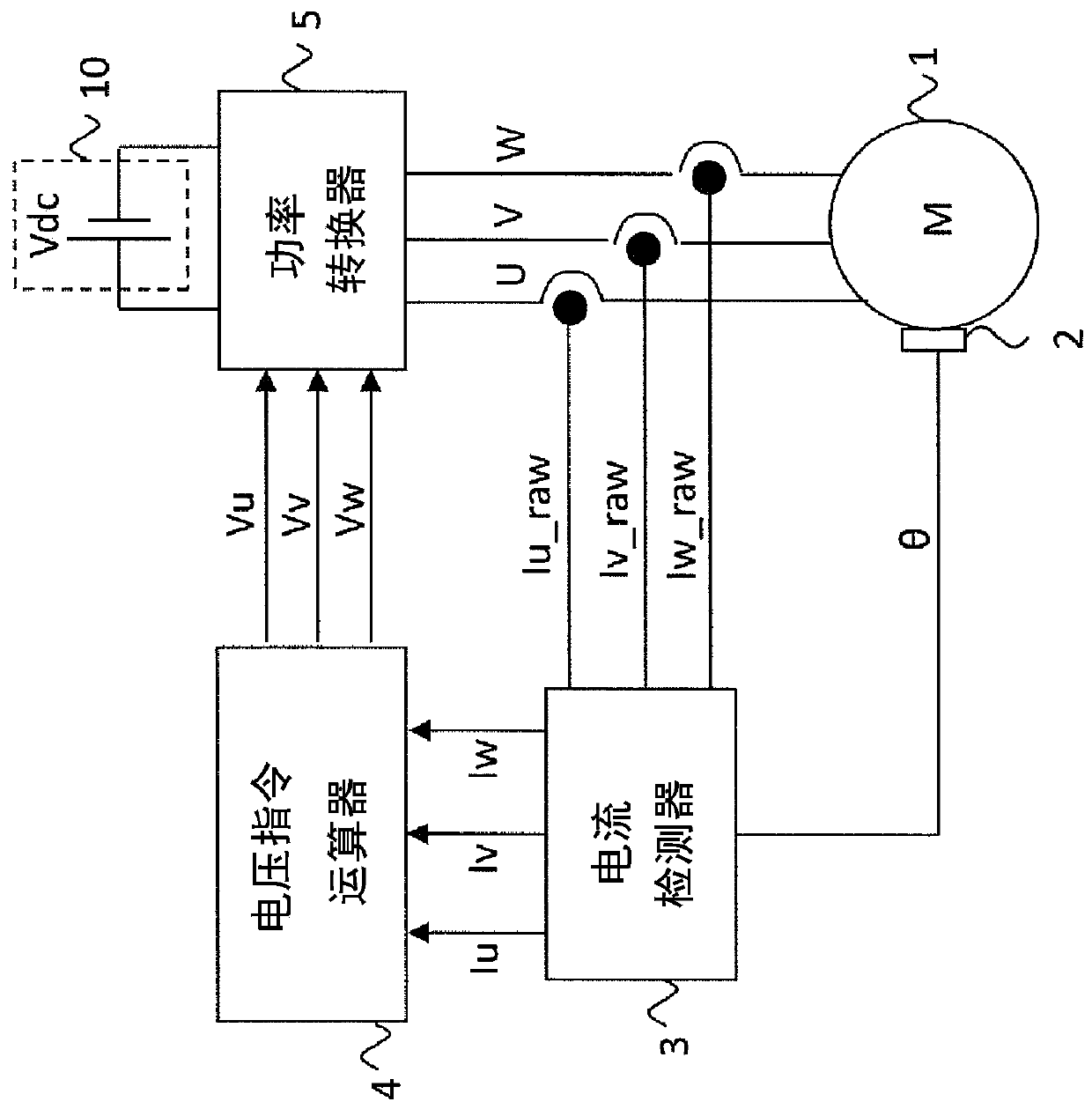
[0027] figure 1 It is a diagram showing the overall configuration of the control device for an AC rotating electrical machine according to Embodiment 1 of the present invention. figure 1 Among them, the AC rotating electrical machine 1 is a permanent magnet type synchronous rotating electrical machine having three-phase windings U, V, W. In addition, in Embodiment 1, a case where a permanent magnet type synchronous rotating electrical machine is used as the AC rotating electrical machine 1 is described, but the AC rotating electrical machine 1 may be a field winding type synchronous rotating electrical machine.

[0028] The DC power supply 10 outputs a DC voltage Vdc to the power converter 5 described later. The DC power supply 10 includes all devices that output a DC voltage, such as a battery, a DC-DC converter, a diode rectifier, and a PWM rectifier.

[0029] The angle detector 2 is a position detector such as a Hall element, a resolver, or an encoder, and detects the r...

Embodiment approach 2

[0088] In the first embodiment above, the above-mentioned formula (5) using an approximate formula of a trigonometric function for a small amount of angle change is used in the estimation calculation. However, in the high-speed rotation region where the angle change is larger, the larger Δθ is, the larger the approximation error is.

[0089] Therefore, by applying the following equation (11) in consideration of the second and second terms in the Taylor expansion as an approximate expression of COS, errors can be suppressed even at high-speed rotation.

[0090] 【Mathematical formula 10】

[0091]

[0092] Figure 7 It is a graph comparing the approximation error with respect to the change in the angle change amount Δθ when using the formulas (5) and (11) in Embodiment 2 of the present invention, the horizontal axis is Δθ [deg], and the vertical axis is the approximation error . In the case of a change of 10 degrees, if the above formula (5) is applied, an approximation err...

Embodiment approach 3

[0104] In Embodiment 1 and Embodiment 2 above, a control device for an AC rotating electric machine having a three-phase winding has been described. On the other hand, in the third embodiment, the AC rotating electrical machine to be applied is generalized as an AC rotating electrical machine having x-phase windings (x is a natural number greater than or equal to 3), and the application of the present invention is based on this. The method of estimation calculation processing will be described in detail.

[0105] Figure 9 It is a diagram showing the overall configuration of a control device for an AC rotating electrical machine according to Embodiment 3 of the present invention. Figure 9 Among them, the AC rotating electrical machine 1a is a permanent magnet type synchronous rotating electrical machine having an x-phase winding. In addition, in Embodiment 3, a case where a permanent magnet type synchronous rotating electrical machine is used as the AC rotating electrical m...


PUM


Abstract

The present invention includes an AC rotating electrical machine with x-phase windings of more than three phases, an angle detector, a current detector, a voltage command calculator, and a power converter. The current detector can detect at least one of the x-phases at this current detection timing. phase current, and the current of up to (x-1) phases cannot be detected, the x-phase detection current obtained based on the past current detection timing, the detection current of one phase that can be detected at the current current detection timing, And the amount of change in angle from the past to the current current detection timing is calculated to estimate the current of the (x-1) phase that cannot be detected at the current current detection timing.

Description

technical field [0001] The present invention relates to a control device for an AC rotating electrical machine and a control device for an electric power steering system capable of reducing current detection errors and resulting torque ripples. Background technique [0002] In the conventional motor control device, by setting the duty ratio of the current undetectable phase to 100%, it is possible to prevent the switching noise of the largest phase whose current cannot be detected from being mixed into the current detection of the two phases other than the undetectable phase. This conventional motor control device estimates the phase current value of the undetectable phase based on the phase current values ​​of two phases other than the undetectable phase (for example, refer to Patent Document 1). [0003] prior art literature [0004] patent documents [0005] Patent Document 1: Japanese Patent No. 5396948 Contents of the invention [0006] The technical problem to be ...

Claims


Application Information

Patent Timeline
Patent Type & Authority Patents(China)
IPC IPC(8): H02P27/06
CPCH02P27/06H02P25/22H02P21/0003H02P21/18H02P21/22B62D5/046H02P6/10H02P2205/05H02P27/12
Inventor 古川晃
Owner MITSUBISHI ELECTRIC CORP
Why Eureka
Try Eureka